Contents
Contents |
|
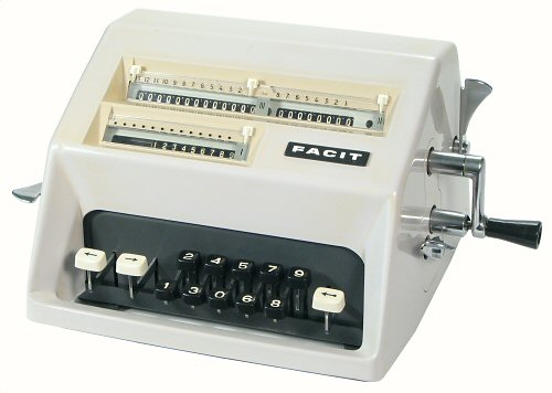
| Facit Model C1-13, c.1970 |
This page gives a brief technical description of the internal mechanism and principles of operation of the Facit C1-13 pinwheel calculator.
Readers may find it helpful to review the following pages before proceeding:
The Facit pinwheel mechanism is similar in principle to the Odhner, but differs in three important areas:
This "inverted" pin-wheel mechanism formed the basis of the Facit model range for almost 40 years. Beginning with the Model T in 9x8x13 format in 1932, the machine progressed through the Model TK (1936) and the NTK (1954) to the C1-13 of 1957, which continued with only minor changes into the early 1970s. The Mechanical Changes page shows some of the progress made during the 40-year development of the 13-digit family.
The same mechanism formed the basis of the first motor-driven range, which progressed through several models into the fully-automatic CA1-13 of 1956. A 16-digit mechanism with back-transfer and a 10-key numeric keypad was introduced as the manual Model CM2-16 in 1959. The fully-automatic CA2-16 followed in 1962, with an updated Model 10-07 in 1967. The 13 and 16-digit mechanisms were both manufactured in parallel until the end of production in about 1973.
The notes following are intended as a general guide to the construction and operation of the Facit C1-13 mechanism. They are also applicable, with only minor adjustments, to most of the hand-cranked 13-digit models (except for the CM2-13S, which uses the 16-digit mechanism). Readers interested in restoring a TK, NTK, or C1-13 to working order will find a step-by-step rebuilding procedure in the Technical section.
I would welcome your feedback, comments, or suggestions for improvement, via the Enquiry Form.
 General arrangement.
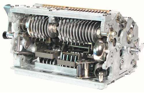
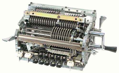
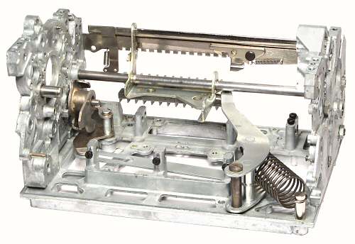
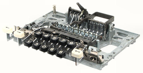
This view shows the C1-13 mechanism with the case and register masks removed.
The keyboard and parts of the rotor positioning mechanism are visible at the front. The pinwheel rotor is towards the centre of the machine, with the accumulator and counter registers behind. The rotor steps to the left as digits are entered, to bring the active pinwheels into alignment with the accumulator dials.
The steel cross-bar immediately above the registers is a guide plate for the numeral wheel detent levers and the carry sensing levers. The sensing levers extend rearwards from the two registers to the carry detent bar at the top rear of the machine. The carry rotor is located directly below the detent bar.
The lever on the left-hand side clears the accumulator register, while that at the right rear clears the counter. The lever at the right-hand front returns and clears the rotor and resets the internal interlocks.
 The base and frame.
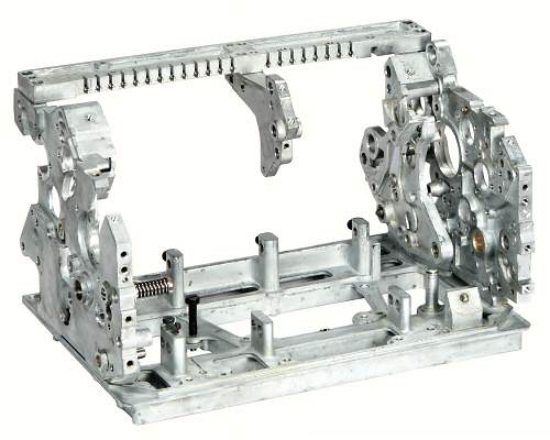
The C1-13 has a substantial frame built from six rather complex alloy die-castings.
The keyboard setting mechanism is assembled on the six pillars in the central region of the base plate.
The setting and carry rotors are supported between the two side plates in removable brass bearings. A small sub-frame plate on the inner right-hand side supports the components of the counter drive and clearing mechanisms. The sub-frame is made from pressed metal on some of the earlier models.
The registers are assembled between the left-hand and inner right-hand plates, with a central support cantilevered from the carry lever detent bar across the top rear of the machine.
 The rotor assembly.
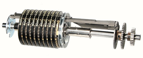
The rotor body consists of nine pinwheels and setting rings and two end plates. The components are keyed and clamped onto a central sleeve, forming a cylinder about 58mm diameter and 64mm long. The rotor body weighs nearly 600g, and moves freely on a ball-slide bearing on a 9mm shaft.
Rotary movement is controlled by a rectangular steel bar (top) which passes through a close-fitting slot in the left-hand end plate. The bar is mounted between two driving discs which are pinned to the rotor shaft. The shaft is driven by the gears on the right-hand end.
The rotor driving bar carries a smaller top bar which locks the setting rings as they move into active positions against the register, and a wedge-shaped section which returns the rings to zero as the rotor is pushed back to its home position at the right-hand side.
Lateral movement is controlled by a travelling carriage (described below) which engages with the groove around the right-hand end plate.
 Pinwheel and setting ring.
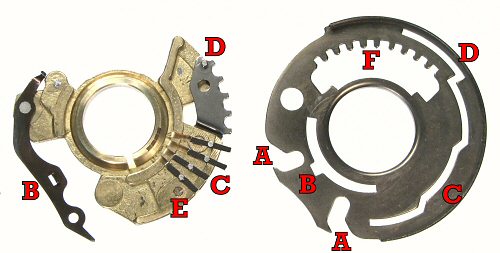
The C1-13 pinwheels are machined from brass castings about 55mm in diameter and 6mm thick, with extensive cut-aways around the setting and clearing mechanisms. The thin sheet-metal setting ring carries painted numerals or a plastic numeral strip around the raised edge. The setting ring sits over the pinwheel and rotates around the raised hub in the centre.
In order to provide a positive short-stroke keyboard action, the pinwheels and setting mechanism (described later) are designed to operate on the bi-quinary principle (ie, two groups of 5, rather than 0 to 9).
At zero, the four sliding pins C are held retracted by engagement with the central section of matching slot C in the setting ring.
Keys 1 to 4 cause a setting arm to move a controlled distance downwards into the upper slot A in the setting ring. This movement releases spring-loaded latch B from its notch and rotates the ring anti-clockwise, advancing one to four pins via the lower ramp in slot C.
For keys 5 to 9, a different arm moves upwards into the lower slot A. This also releases latch B, and turns the ring in the opposite direction. Slot D advances a 5-tooth sector in one movement at the first step. (The right-angle step at D appears to make this impossible, but the angle is actually quite mild relative to the sector's pivot point at E). With further rotation sector D remains extended, and slot C advances one to four pins via the upper ramp. The pinwheel is shown with a setting of 7.
When the escapement is released and the rotor steps to the left, the top-most slot at F moves onto the locking bar to secure the setting. When the rotor is returned to its home position, the rings move back past the locking bar, and the clearing wedge acts on the edges of the cut-out F to return the rings to the central position. Latch B springs back into its notch to hold the rings at zero.
 Rotor pin alignment.
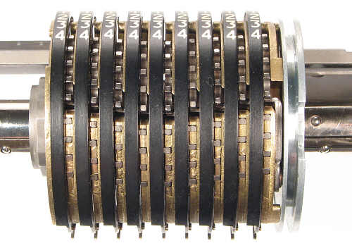
The pinwheels and setting rings are not all the same. The small offsets between adjacent wheels allow the register detents to operate at slightly different times, providing a smoother and less "clunky" rotation.
There are five different (numbered) pinwheels and setting rings, which must be assembled in matching pairs and in the correct sequence. The sequence as shown is 2-3-4-5-5-4-3-2-1 (left to right), but re-assembly actually starts with number 1 on the right. Pinwheels 1 and the first 5 have two short fixed pins mounted in the upper cut-away to act as guides for the clearing wedge.
 Rotor bar detail.
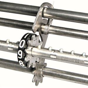
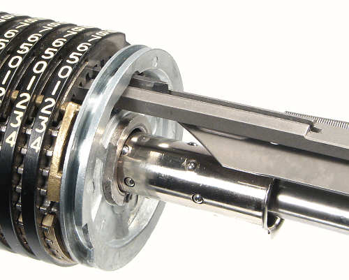
This view shows the rotor driving and locking bars in more detail. The rotor's home position is fully to the right, with its leftmost pinwheel just to the right of the tapered end of the top locking bar. As the pinwheel is set, the rotor steps to the left and the setting ring moves onto the bar. The engagement is visible under the 6 on the first ring.
The rotor is cleared by pushing it back to the right. As the setting rings move clear of the locking bar, they move onto the the clearing wedge and are pushed back towards zero, where they are held by their internal latches.
As the clearing lever is operated, an arm pushes the clearing wedge about 3 places inwards to ensure that it engages fully with the leftmost pinwheels. The locking bar moves with the clearing wedge via a connection through the slot in the main bar, and is returned by the spring visible behind the bar.
 The rotor carriage.
This view of the rotor carriage is taken from the rear of the machine.
The carriage slides on a 7mm steel shaft between the two frame side plates. It is supported by a curved vertical arm which hooks over a flat pressed-metal bar across the front of the machine. The vertical arm engages with the slot in the right-hand rotor end plate (see view above).
The carriage is urged towards the right (in this rear view) by the large spring and arm at the right-hand side, but is restrained by the toothed bar on its underside which engages with an escapement on the top of the keyboard setting mechanism. The escapement releases the carriage in two half-steps as each numeral in entered.
The small lever on the vertical arm of the carriage normally rests in the notch in the rotor end plate (view above). When the rotor begins to turn, the far end of the lever is cammed into engagement with one of the notches in the front supporting bar to lock the carriage in position.
The division setup key releases the escapement and allows the rotor to run freely to the end of its travel, where it is caught by a latch on a sliding lever on the inside of the front cross-bar. The latch is only active when the lever is pulled down by the division key. A buffer spring on the side plate (hidden) absorbs the kinetic energy, and the latch prevents the rotor from bouncing back.
The clearing handle at the front right of the machine pulls the rotor back to its home position through the two orthogonal levers and rollers and a connecting link to the spring arm. The carriage is held in the home position by the keyboard escapement.
 The keyboard assembly.
The keyboard mechanism is assembled on the six pillars on the base plate. Two 5mm shafts through the front pillars support the keys and the rocking escapement plate (described below). Three short pins through the rear pillars support the two setting arms. The left arm moves down for keys 1 to 4, while the right arm moves up for 5 to 9, as previously described. (The zero key also moves the left-hand setting arm to maintain a consistent touch, but it does not affect the pinwheels).
The two white keys at the left move the carriage one place to the left or right. The division setup key at the right-hand side releases the escapement and allows the rotor to run fully to the left.
The numeral keys are held upright by two slotted guide plates at the front and centre. A "swinging arm" mechanism on the rear of the front guide plate ensures that only one key can be pressed at a time. The keyboard is interlocked with other machine functions by two sliding aperture plates on the front of the front guide plate, and by other mechanisms acting on the setting arms. All of the interlocks are reset when the rotor is cleared.
 The keys.
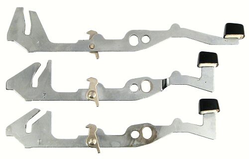
This view shows typical keys for 1, 5, and 9. The key numbers are clearly stamped at the rear so that they can be identified without their keytops. The long and short keys have separate pivot shafts.
As the front of the key is pressed, the graduated slot at the rear lifts the setting arm through a controlled distance. The notch at the bottom of the slot locks the arm to prevent overshoot the end of the stroke.
Each key has a small swivelling hook which locks it onto the escapement mechanism (see Escapement (2) below).
 The escapement mechanism (1).
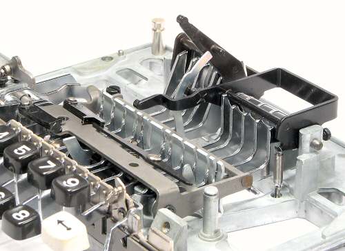
The lower portion of the escapement mechanism consists of a rectangular frame which is mounted above the keys and pivoted on the front support shaft.
The flat section across the front of the frame carries two spring-loaded pawls at the left-hand end. The rotor carriage is normally restrained by one of the teeth on its underside resting against the front pawl.
The rear of the escapement frame consists of a square bar which rests on the tops of the keys, just behind the central guide plate. A spring holds the bar down against the keys.
This view also shows a lever which interlocks the setting arms with the carriage position. The front of the lever (behind the 5 keytop) rides on a camming surface at the front of the rotor carriage. The lever passes under the escapement frame and rises to engage with the setting arms at the rear. The lever blocks the movement of the setting arms unless the carriage is in one of its locked positions.
 The escapement mechanism (2).
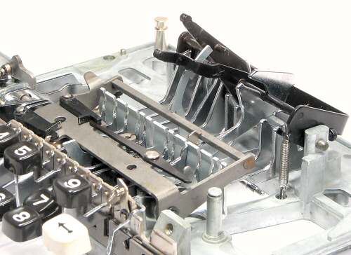
When a key (eg 7) is pressed, the setting arm moves up into the space between the pinwheels and turns the active setting ring to the corresponding position. The keystem raises the rear of the escapement frame, and the curved face of the central guide plate cams the keystem hook rearward to lock the key onto the square bar.
As the escapement frame rocks forward, the front pawl moves clear of the tooth on the rotor carriage. The carriage moves to the left, until blocked by another tooth striking the rear pawl. This half-step is sufficient to disengage the setting arm from the ring, but the arm is still raised between the rotor discs.
When the key is released, the spring on the escapement frame pulls the frame, key, and setting arm back to their home positions. At the end of this movement, the rear pawl disengages, and the carriage steps across until stopped by the front pawl again.
The impact of the carriage against the pawls is taken through the right-hand side of the escapement frame, which rests against a shoulder on the front key pivot shaft. The far end of the shaft rests against an adjustable stop in the left-hand side plate. The stop must be set so that the rotor aligns correctly with the setting arms and the accumulator register.
The left-shift key raises and drops the escapement frame to complete a full step without affecting the setting. The division setup key raises the escapement frame, and at the same time withdraws the rear pawl via a short arm acting on the cross-ways lever. When the front pawl disengages, the rotor is free to run fully to the left.
 Register detail.
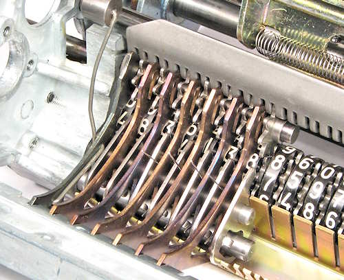
This view shows the arrangement of a single register column.
The numeral wheels are driven by the star wheels below, and are held in position by the spring-loaded detent levers above.
The star wheels are driven by the setting rotor or counter drive pawl at the front, and by the carry rotor at the rear.
The register shaft is drawn sideways to engage the clearing teeth with corresponding teeth on the inside of the numeral wheels.
Slotted guide plates top and bottom keep the levers and star wheels properly aligned with the register.
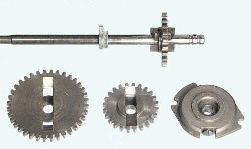
 Register components.
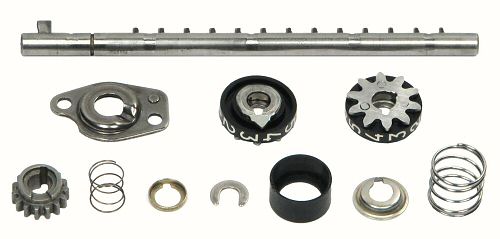
This view shows both sides of the numeral wheels, with the driving star wheel on the right and the carry setting tooth on the left. The two metal parts are rivetted together with the plastic numeral wheel between. Earlier machines used a light metal numeral wheel with painted numbers.
The other components in this view are involved with clearing the register. The two registers are identical, except for the shaft and cam plate. Those shown are from the accumulator side - the counter parts are shown in the next view.
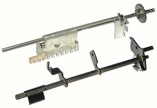
 Register clearing mechanism.
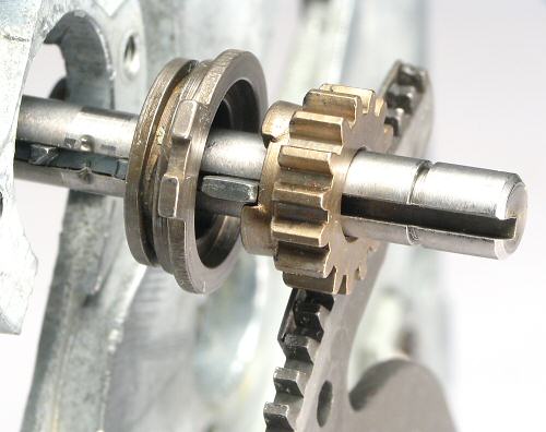
This is a partial view to show the operation of the clearing mechanism. The C-clip (view above) fits in the groove near the end of the shaft, with the dished washers and springs on either side. The small spring pushes the brass gear to the left, while the large spring pushes the whole shaft to the left. The shallow notch at the left of the gear engages with the broad pin on the register shaft.
As the clearing sector moves forward, the brass gear rotates clockwise. A ramp inside the cam plate pushes outwards on the broad pin and moves the shaft about 2mm to the right.The clearing teeth pick up the numeral wheels and return them to zero as the shaft rotates. Note that the pin also pushes the brass gear outwards, sliding it across the face of the sector.
When the shaft completes a full turn it springs back to the left as the pin drops into its home position in the cam plate. The gear is unable to follow, as its path is blocked by the shield plate on the left-hand side of the sector teeth. With the pin clear of the driving notch, the gear turns freely as the sector rises on the return stroke.
The gear springs back against the pin when released by the shield plate, and drops back into the notch at the end of the stroke.
 Carry sense components.
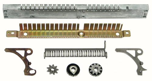
The die-cast carry lever detent bar (top) ismounted across the top rear of the machine. The slots guide the tails of the carry levers (bottom left and right), and the captive spring-loaded pins latch them up or down.
The pressed-metal upper guide plate positions the register detent levers and the centres of the carry levers. The lower guide plate positions the lower ends of the carry levers, and keeps their operating ramps close to the adjacent star wheels.
There is no room for a lower guide plate on the counter side, as the space is occupied by the travelling drive pawl (see below). The bottom ends of the carry levers are modified to engage with locating slots cut into the star wheel shaft.
 Carry lever installation detail.
This view shows the carry levers partly assembled, looking from the rear with the machine inverted.
Carry levers, star wheels, detent levers, and detent lever springs are installed one at a time in sequence across each of the registers. The spring tails are attached last.
The leftmost carry lever operates the overflow bell. The bell hammer (top left) is mounted on a length of heavy spring wire, which is threaded through two holes in the lever and crimped into place.
 The carry rotor.
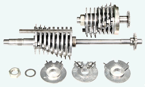
The carry rotor has two separate sections mounted on concentric shafts. The accumulator section always rotates in the same direction relative to the setting rotor, but the counter section can rotate in the opposite direction when the register is reversed during division. Each section has two rows of staggered pins to allow ripple carries in either direction.
The rotor is built up from a series of die-cast discs with the operating pins set at graduated angles. The discs are identical in each section - the accumulator has discs 1 to 12, while the counter has 1 to 4 and 10 to 12.
The eccentric outer edges of the discs act as camming surfaces to reset the carry levers as the rotor returns to its home position.
 The carry rotor installed.
This view shows the carry rotor in position at the rear of the machine.
The division bell (centre right) is operated by a small hammer attached to the last carry lever on the accumulator.
 The drive train.
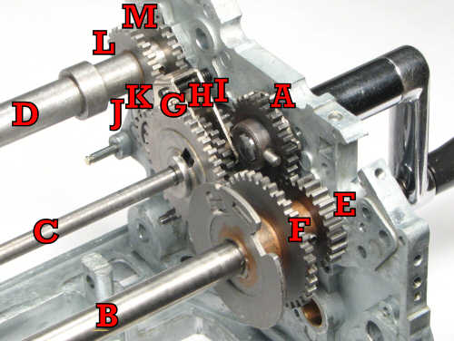
The drive train has one input A from the winding handle, and four outputs to the setting rotor shaft B, the counter drive shaft C, and the two concentric carry rotor shafts D.
Gears E and F are fixed to the setting rotor shaft. G, H, and I are mounted on the counter drive shaft. Gear H is fixed to the shaft, while G and I are mounted loosely. J and K (partly hidden) are small intermediate gears which drive the carry rotors through gears L and M.
The winding gear A is permanently coupled to the setting rotor through gear E, and to the accumulator carry rotor through gears I, K, and M. The setting rotor and the accumulator carry rotor always rotate in the same relative directions.
Gear I is driven directly from A, while G is driven via E and F. Gears G and I therefore rotate in the opposite directions. Gear H can be coupled to either G or I to drive the counter in either direction. Gear H then drives through the double-width intermediate gear J to the counter carry rotor gear L, so that the counter drive pawl and the carry rotor both reverse together.
A thin disc carrying a "full-cycle" or "non-return" pawl is fitted between gear A and the side plate. Its purpose is to prevent errors due to incomplete carries, by ensuring that a turn must be completed after it has advanced more than about 30°. If a machine jams during a turn, it is often possible to "back out" by releasing this pawl manually. The calculation in progress must be discarded.
 The counter reversing mechanism.
The counter register is required to count forwards during division, even though the winding handle is being turned backwards. The reversing mechanism automatically sets the relative directions according to the first turn of the handle. This section describes the mechanism in more detail.
The counter drive shaft extends across the full width of the machine. It is supported in a plain bearing in the left-hand side plate, and in the steel bearing (lower right) at the right-hand side. The single-tooth drive pawl is keyed to the shaft, but is free to slide lengthways to engage with any of the counter star wheels.
The two contra-rotating driving gears are mounted loosely over the shaft, with the large slots facing the rectangular cam blocks on either side of the central gear. The outer gears are held apart by a light spacer bracket. The central gear can move sideways to engage the cam blocks with either of the driving gears. A spring-and-ball detent in the bottom of the right-hand bearing holds the the shaft in either position by engaging with the two grooves near the end.
When the counter register is reset, a V-shaped lever rises under the central gear and returns it to its starting position mid-way between the two driving gears. The detent ball engages with a small dimple between the two grooves to hold the shaft in its home position. With the gear in this central position, the cam blocks are aligned and half-way engaged with the slots on both sides.
If the handle is turned forward (CW from the right), the right-hand gear will turn CCW and will drive the central gear in the same direction via the wide faces of the right-hand cam blocks. At the same time, the left-hand gear will turn CW. The ramped faces of the left-hand cam blocks will push the central gear to the right until it is fully engaged with the right-hand gear and completely disengaged from the left. It will remain in this position until the counter register is cleared. If the first turn was backwards, the central gear would be pushed to the left and would drive the counter in the opposite direction.
The setting of the counter direction is completed in the first 20° of handle movement, well before the non-return pawl engages at 60°. This allows a short-cut multiplication to be commenced with a negative turn, provided that the handle is first turned a few degrees forward to set and lock the counter into the positive direction.
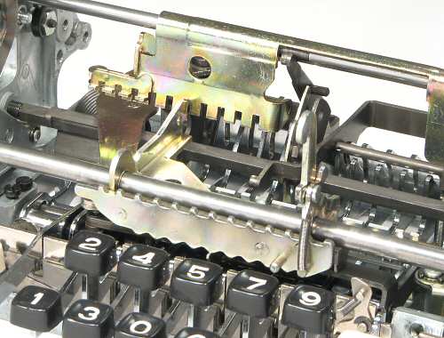
 The sliding quotient coupling.
The counter operating pawl is positioned along the drive shaft by a sliding plate which can be rocked forward to couple it to the rotor carriage. Fore-and-aft movement is controlled by a bar which engages with the forked arm on the square shaft below. The plate is normally held rearward and disengaged from the carriage. A light spring holds the plate against a stop on the right-hand side, so that the pawl sits under the rightmost star wheel.
On multiplication, the carriage steps to the left as the first factor is entered. When the handle is turned, a cam and lever in the drive train rotate the square shaft and push the coupling forward, bringing one of the notches into engagement with a rearward arm on the rotor carriage (see next view). The counter drive pawl then follows the rotor as it is stepped to the left for succeeding digits. Five to eight places will be available, depending on the length of the first factor in the rotor. An indicator plate (not shown) connects to the right-hand end of the sliding plate to show the current active position. Note that the stop at the right-hand end of the coupling makes it impossible for the rotor to be stepped back to the right beyond the point at which the coupling was engaged.
On division, the setup key brings the coupling to a half-forward position. This does not engage the teeth, but brings a small plate at the left of the coupling (see next view) into the path of the carriage arm. As the rotor runs to the left, the arm stikes the raised plate and draws the coupling along. When the rotor stops at the far left, there will be 5 to 8 places free at the right-hand end of the coupling, depending on the length of the divisor. The coupling engages fully when the rotor begins to turn, so that the counter pawl follows the rotor as it is stepped back to the right.
 The quotient coupling installed.
This view shows the quotient coupling and the square shaft installed in the machine, with the coupling fully engaged with the carriage horizontal arm.
Several features of the carriage front plate are also visible in this view: