Contents |
|
This page shows some of the major mechanical changes made to the Facit 13-digit calculator during its 40-year development.
If you find other significant differences I would welcome your feedback via the Enquiry Form.
The right-hand side plate clearly shows the gradual changes in the development of the frame. Similar changes are found in the left-hand side and in the baseplate.
 Early TK
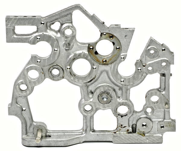
This view shows the inside face of the right-hand side plate of a very early TK.
The four large circular circular openings are the bearing housings for (left to right) the carry rotor, the counter drive shaft, the winding handle, and the pinwheel rotor. The large handle stop post (directly below the handle bearing) is permanently riveted in place, but the pivot for the intermediate gears (at the top of the large cutout) is removable. The large cutout provides access to the pivot post for the counter reversing reset lever. The post at the bottom rear is a spring attachment point.
The side plate is a rather elegant casting which weighs only about 170g, but it is a little too susceptible to damage. Problems occur at the bottom rear corner, and where the top rear shelf is weakened by the adjacent screw holes.
 Later TK and NTK
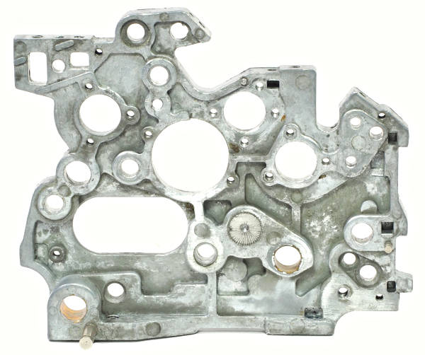
This side plate from a later TK has been greatly strengthened and is about 40% heavier than the earlier model.
Obvious changes are the smaller cutout, the larger counter drive shaft bearing, and the location of the spring attachment post. A machined hole has been added at the bottom rear but is not used in the hand-cranked machines.
This design was introduced fairly early in the TK production run, and was carried over into the NTK.
 Early C1-13
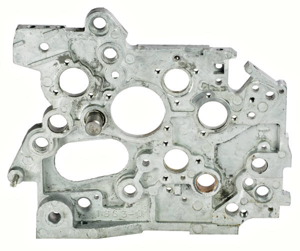
The early C1-13 side plate is stronger and heavier again.
The major changes are that the intermediate gear pivot is now permanently riveted, and the handle stop post is removable and (later) adjustable.
The spring anchor post has been relocated, and various other holes (mostly un-used) have been added, deleted, or relocated.
 Late C1-13
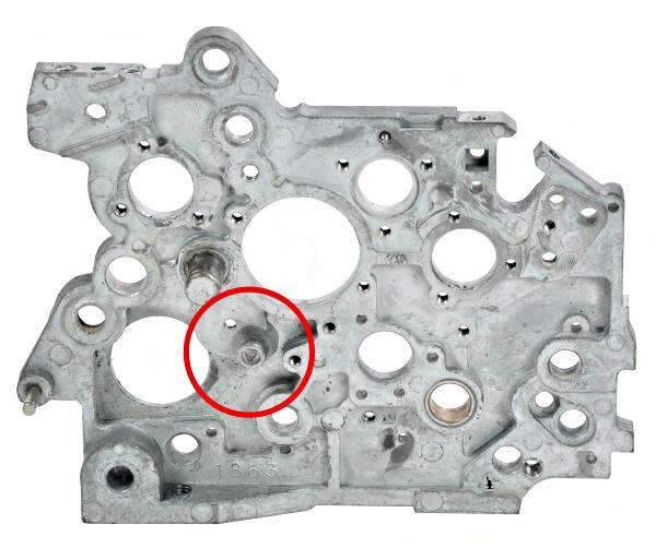
The only change in the late C1-13 side plate was to further reduce the bottom rear cutout and to provide a stronger pivot for the counter reversing reset lever. The new design has a substantial bushing on the inside of the side plate and a pivot pin which can be removed from the outside.
Despite the many detail changes, the basic geometry of the machine (bearing and control locations, etc) has not changed from the original version.
This section shows four verions of the interlocks at the front of the keyboard. Please click the photos to enlarge further.
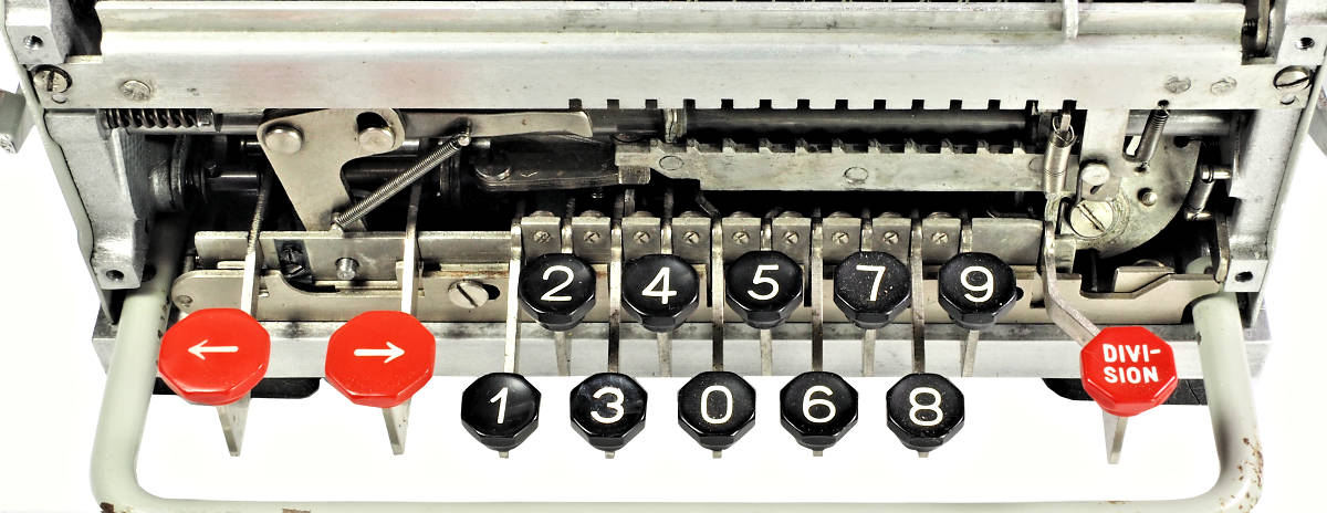 Very early TK (1937)
This very early TK has two sliding aperture plates under the fronts of the keys. The front plate locks the entire keyboard while a rotor clearing operation is in progress. Conversely, and more importantly, it prevents a clearing operation if any key is partly down and the setting arm is still engaged with the pinwheels. A separate mechanism prevents the rotor turning during clearing, and also prevents partial clearing operations.
The rear aperture plate locks the right shift key until either of the left shift keys has been pressed. It then releases the right shift key and locks the numeric keys. The locks are reset by a pin on the rotor clearing arm when the clearing handle is operated. A small spring plate (near the left shift key) holds the aperture plate in either position.
There is no interlock between the keyboard and the winding handle. It is possible to enter further digits after the handle has been turned, or to perform a left shift in adding-machine fashion by pressing the Zero key.
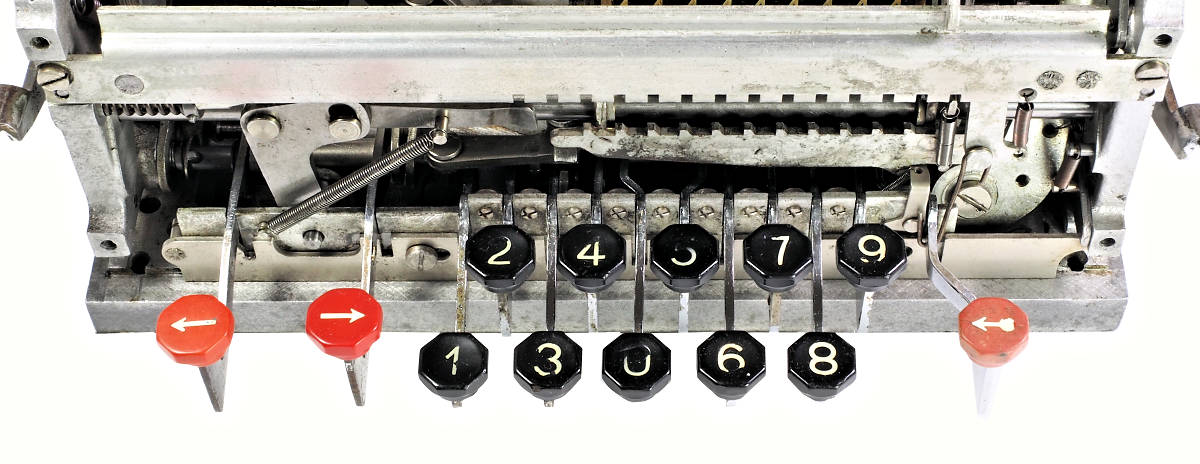 Early TK (1941)
This 1941 TK has only a single aperture plate, which now has a small latch lever behind the 9 key. The plate will prevent a rotor clearing operation if any key is partly down, as described above. A normal clearing operation will lock the keyboard and engage the latch. The keyboard will remain locked until the rotor returns fully home and releases the latch.
Operating either of the left shift keys will lock the numeric keys and release the right-shift key. The latch will engage and the keys will remain locked until the rotor returns fully home.
Although unrelated to the interlocks, compare the arrangement of the spring on the pair of levers behind the right-shift key with the early machine above. In the first machine the spring is connected between the two levers, and there is a separate torsion spring holding the levers anti-clockwise. In the later machine the lower attachment point has been moved about 10mm from the bottom lever onto the key guide plate. The tension spring now performs both functions and the torsion spring has been deleted.
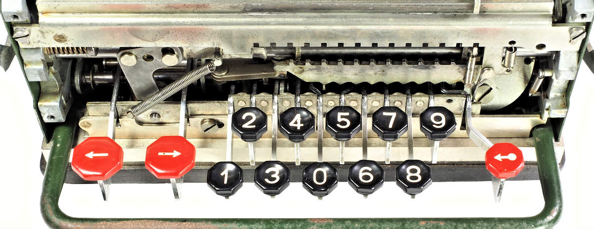 Late TK (1948)
This 1948 TK has only a single aperture plate and no latch, although the latch engagement tab is still present. The plate's only function is to interlock the keyboard with the rotor clearing, as described above.
Locking the keyboard when the handle is turned, and locking or releasing the right-shift key are now handled by changes to the interlock shaft at the rear of the machine.
Note also the "wave" profile added to the bottom edge of the rotor carriage. A light lever (between the 0 and 5 keys) rides on this profile and rises and falls as the carriage moves along. The far end of the lever blocks the movement of the setting arms unless the carriage is positioned exactly with the lever on the peak of a wave.
A further change visible in this picture is the small tab added to the bottom edge of the front cross-bar (above the 2 key). This tab presses down on the spring attachment pin on the right-shift lever to prevent the lever rising and becoming disengaged during a shift.
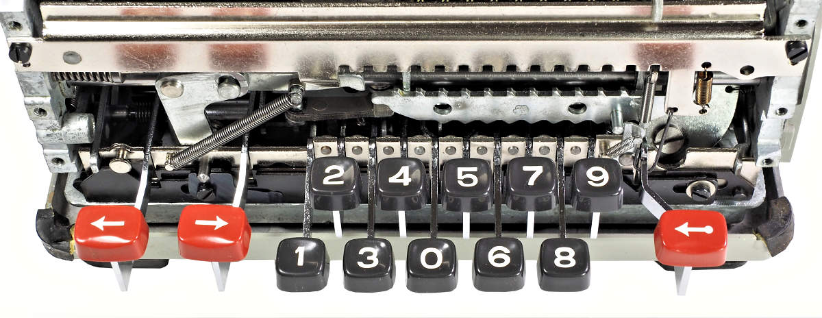 C1-13 (1965)
The C1-13 keyboard takes a "belt and braces" approach with two aperture plates and a latch lever. The rear plate interlocks the keyboard and rotor clearing as described above, and the latch keeps the keyboard locked until the rotor returns fully home.
The front aperture plate locks the numeric keys when the rotor starts to turn, complementing the function of the interlock shaft which blocks the movement of the setting arms. The front plate is reset when the shift keys are pressed, but the numeric keys remain blocked until the rotor is cleared.
The tab under the front cross-bar has been modified and the pin has been provided with a tiny hardened roller.
 TK, NTK, and C1-13
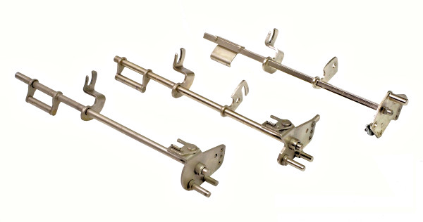
The original purpose of the rear cross-shaft was to engage the quotient coupling when either a left shift or a movement of the crank signalled that digit entry had been completed. The shaft soon acquired more functions relating to the interlocking of the rotor, keyboard, and setting mechanism.
The three shafts shown are from a very early TK, a later TK, and a C1-13. All three have a bar or plate at the left (operated by the left shift key), and an offset forked arm which engages the quotient coupling. Pressing the key rotates the shaft anti-clockwise, pushing the coupling forward and engaging it with the rear arm on the rotor carriage.
The later TK and C1-13 shafts have an additional plate which works in conjunction with the keyboard aperture plates to control the movement of the right-shift key, the numeric keys, and setting arms.
The 3-position detent plate at the right-hand end is coupled to the winding mechanism, and is reset by the rotor clearing mechanism. The detent plate and its connections were redesigned for the C1-13.
 Very early TK
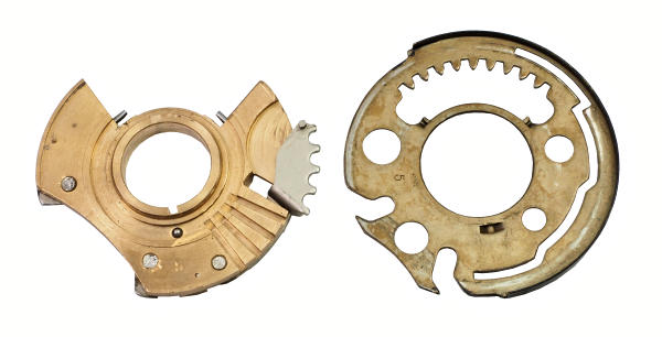
The Facit pinwheels have no detents, and those on the very early TKs have no zero latch. The rings are held in position by a locking bar at the top of the rotor, and are only able to turn when they reach a gap in the bar at the setting position. There is nothing to stop the discs from turning while in position and waiting for a keystroke.
The underside of the very early pinwheel carries two spring-loaded guard plates. Their purpose is not obvious, and they were soon deleted. The #5 disc shown has two guide pins in the upper cutout to assist the movement of the clearing wedge.
The setting rings are mounted directly over the hub of the disc. These early rings have two small turned-up tabs in the upper opening to increase the contact area where they engage with the clearing wedge.
 Later TK
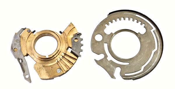
The later TK pinwheel has deleted the guard plates and added the spring-loaded zero latch. The setting ring has gained a matching slot with a notch at the zero position, and has lost the two clearing tabs. The clearing wedge acts directly on the edge of the cutout, and sometimes causes considerable wear.
In some machines a thin steel band is fitted around the hub of the pinwheel to resist abrasion from the setting ring.
 Late C1-13
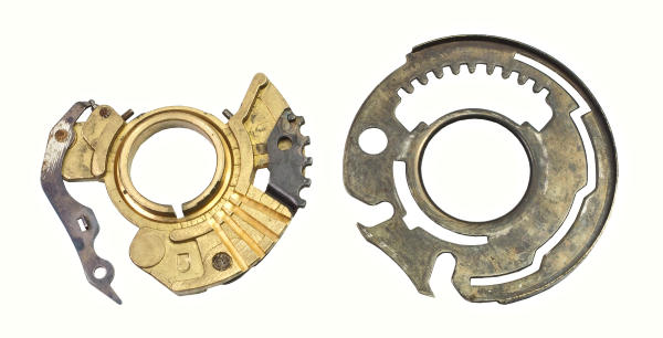
The pinwheel from the late C1-13 has a deep groove around its hub. The setting ring has a drawn-down centre which engages with the groove to provide a much wider bearing surface.
 TK and C1-13
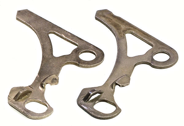
The carry lever is set by the numeral wheel acting on the point at the centre right, and re-set by the carry rotor acting on the point at the bottom left. It is held in either position by the pin in the detent bar acting on the point at the top left.
Setting the carry lever brings the trapezoidal ramp (bottom centre) into the path of the carry rotor pin, which then transfers the carry to the next decade. In early machines the ramp is made as a separate part which is riveted to the carry lever. In later machines the lever is a single piece with the ramp cut and pressed in place.
 Early TK
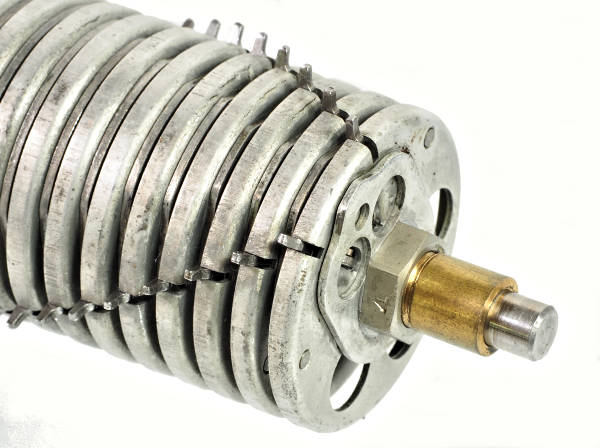
In the early TK the carry pins are mounted on a series of circular pressed-metal discs. To the right of each disc is a flat pressed-metal cam which re-sets the carry lever as the rotor returns to its home position. The discs and cams are keyed to a brass core which is pinned to the 8mm steel shaft. The discs are separated by spacers. A long locating rod passes through all the discs (on the side opposite the cams) to maintain exact alignment.
The carry pins have individual leaf springs riveted to the discs.
 Later TK and NTK
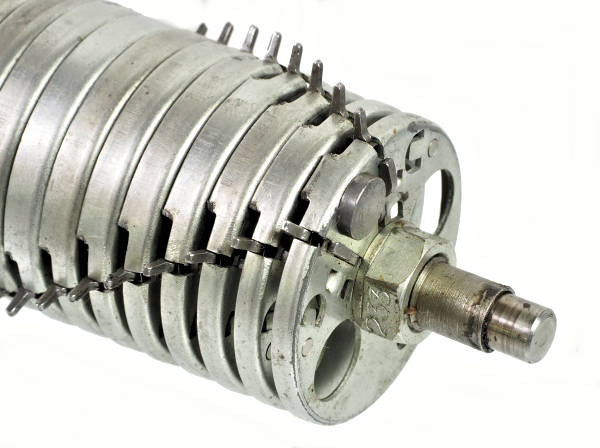
In later TKs and NTKs the separate reset cams were deleted and replaced with a one-piece disc and cam. The discs were drawn deeper, and most of the extended section was cut away. The section remaining provided a cam surface similar to the previous cam on the left. A pin or disc was riveted to the end disc to reset the last carry lever. The previous brass core was replaced with steel.
No attempt was made to ease the sharp edges where the cut-away cam surface contacts the carry lever. The rotor shown has only mild wear on the cam edges, but others can be seriously worn. The hardened carry levers rarely show any significant wear.
 C1-13
C1-13
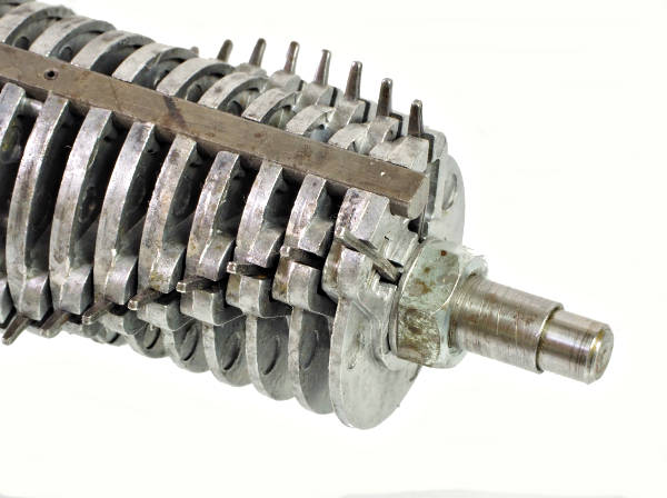
The C1-13 carry rotor has die-cast discs with embedded coil springs for the pins. The discs are keyed onto the steel sleeve and have an alignment rod set into the circumference at the home position. In some machines the keys and keyway are cut at a slight angle so that the discs can not be assembled upside down.
The discs only have their full diameter at the pins and at the home position. The "un-used" part of each disc is reduced in thickness and diameter to save material. A sloping cam surface is formed on the approach to the home position so as to gradually reset the carry lever.
 TK and NTK
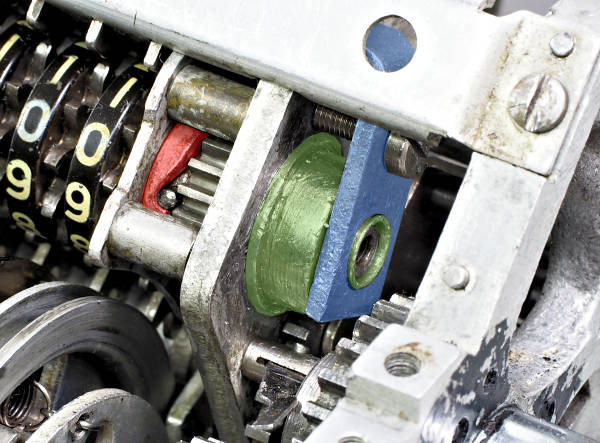
In the TK and NTK the counter register cam plate (red) is mounted from the pressed-metal right-hand sub-frame. A small cover (greeen) is set into the sub-frame to contain the spring and to provide an outer bearing for the register shaft. The L-shaped bracket (blue) retains the bearing and also provides an end stop for the carry and detent lever shafts.
 Early C1-13
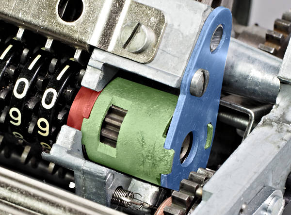
The C1-13 has a die-cast sub-frame and a removable cam plate, allowing the register to be removed and replaced as a complete assembly.
In this early C1-13 the cam plate (red) is keyed to a thick sleeve (green), which in turn is keyed to a retainer plate (blue) to set the angular alignment of the cam. The sleeve also contains the register spring and other components for the redesigned clearing mechanism. The carry and detent lever shafts now have a separate retainer at the opposite end.
On disassembly the cam plate can be moved to the right until it is clear of the sub-frame, so that the shaft (with register attached) can be lifted out through the slot.
 Later C1-13
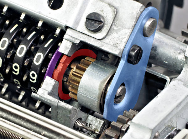
In later C1-13s the keyed retaining sleeve has been deleted. The cam plate is aligned by a tab engaged with the slot, and is retained by a large C-clip (purple) on the left of the sub-frame. The retainer plate (blue) only retains the spring, which is covered with a light metal or plastic sleeve.