 The Addition Mechanism.
The heart of the Madas calculator is the stepped drum or Leibnitz wheel, invented by the German philosopher and mathematician Gottfried Leibnitz in about 1670. Leibnitz built several machines using this principle, but never adequately solved the problem that has confounded all calculator builders since - how to achieve a reliable "tens-carry" from one decade to the next.
The Addition Mechanism.
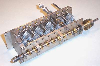
In the Madas, the ten stepped drums have been reduced to quadrants and interleaved to produce an extremely compact assembly only 160mm wide. The mainshaft at the front of the assembly rotates all of the drums in unison via bevel gears. The square shafts above the drums (only one shown for clarity) transfer the results via the differential gears (rearmost) to the result register in the carriage.
The mainshaft always rotates in the same direction (clockwise from the right-hand end). Subtraction is accomplished by sliding the differential gearset along the shaft so that the opposite side engages with the carriage.
The shaft extending rearwards from the first quadrant drives the carry camshaft and the carriage shift and clear mechanisms (see later). Note that this quadrant has steel drive gears - the other nine have brass.
 Detail of the stepped drum assembly.
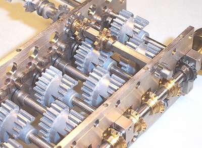
Links from under the keyboard (not shown) rest in the collars on the brass pinions and slide them into position along the square shafts. The positioning is very precise. The front pinion can engage 0 to 5 teeth on the drum, the rear engages either 0 or 6 to 9. As the drum rotates, the transfer shaft advances by the required number of steps. (There are 10 steps per revolution, or 36 degrees per step).
Behind the rearmost sliding pinion is a spring-loaded detent wheel, and under this is a locking pawl driven by a cam on the end of the quadrant shaft. The transfer shaft is normally locked, and is only released during the addition or carry phases of the cycle.
On the far side of the back plate are the carry pinion with its locating collar, and the differential gearset.
The small gear on the front of the square shaft is used to transfer data into the multiplier unit.
 The Carry Mechanism.
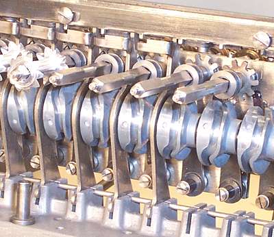
The carry mechanism is located immediately behind the stepped drum assembly and below the carriage. The rear plate and carriage have been removed for this photo, and the mechanism is only partly assembled to show its components more clearly.
The differential gears and carry pinions can slide along the square shafts. The carry sense levers pivot on the wire at the bottom, and move about 2mm front-to-back in guide slots in the detent bar at the top. Spring-loaded balls hold the levers in either front or back position. A pin on the side of the sense levers engages with a collar on the next carry pinion.
The carry operating fingers are attached to the screwed pivots, and are moved side-to-side by pins engaging in the slotted cams. The carry camshaft rotates in unison with the mainshaft. The fingers are normally to the left, clear of the carry pinions, and move across to a position vertically below the corresponding transfer shaft as the carry camshaft rotates. Note that the slotted cams are timed sequentially, so that a ripple carry can propagate across the entire machine.
A sliding shutter on the face of the detent bar blocks the movement of the carry sense fingers when the machine is at rest, preventing inadvertent entry of a carry if the numerals are entered or adjusted manually.
 Detail of Carry Operation.
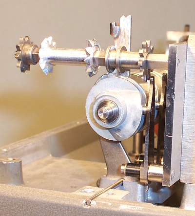
The carry sense levers are normally held in the rearward position as shown, so that the carry pinions are held clear of the operating fingers. The carry fingers sweep side-to-side in sequence on every machine cycle, but nothing actually happens unless a carry is required.
The carriage register is driven by a bevel gear on a vertical shaft (not shown) above the differential gears. When the register moves from 9 to 0 (or vice versa), a finger on the vertical shaft pushes forward on the horizontal tab near the top of the carry sense lever. The ball catch latches it into the forward position via the notches at the top.
With the sense lever forward, the carry pinion is aligned with its operating finger. As the camshaft rotates, the shaft lock is released, the carry finger pushes the pinion exactly one step forward, and the lock re-engages. A pin on the far side of the slotted cam then pushes the sense lever rearward to its original position. The carry pinion is again clear of the operating finger, which is driven back to its home position as the carry shaft rotates further.
The add-and-carry process is completed in a single rotation of the mainshaft. Addition occupies about one third of the cycle, from 50 to 170 degrees rotation. The carries occur in sequence from 220 to 320 degrees. All of the sense levers are reset by the end of the cycle, although the last of the operating fingers do not return home until about 50 degrees into the next cycle.
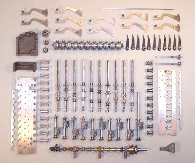 Component Parts.
The add-and-carry mechanism is assembled from these 80 components, which contain almost 500 individually manufactured parts.