 The keyboard connecting links.
The keyboard and its display register (Register III) form a self-contained module that is easily removed from the machine. The keyboard module contains over 600 manufactured parts.
The keyboard connecting links.
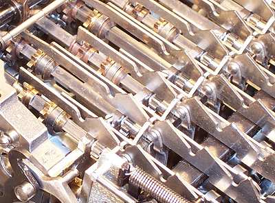
These pairs of ramped connecting links translate the keyboard setting into the fore-and aft positioning of the sliding pinions in the addition unit.
Pins on the bottoms of the key stems press downwards on the steep side of the ramps as the key is depressed, sliding the link forward (to the right in the illustration). The key latches at the bottom of its stroke, holding the link securely in position via the pin engaging with the notch at the bottom of the ramp. All the keys travel the same distance - it is the ramps and notches that are graduated to position the sliding pinions.
The connecting links are held laterally in guides front and rear, but are supported vertically by a parallelogram linkage to minimise friction. The 40 supporting arms are pivoted on cross-rails in the bottom of the multiplier unit.
 Key stems and Register III
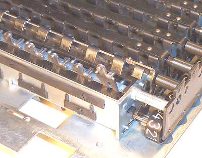
This view from under the keyboard shows the bottom end of the key stems, and the short pins which operate the connecting links.
The tags extending behind the key stems raise one or other of the graduated fingers on the rocking bar above, rotating it and the Register III numerals via the spring-loaded sector gear and pinion at the front.
The screwed plates on the side of the keyboard are retainers for the various internal shafts and rails.
 The keyboard internal mechanism
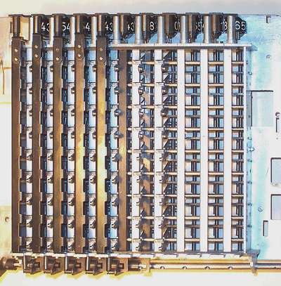
In this (underneath) view the keyboard is partially assembled in stages to show its internal construction.
The three columns to the right are empty, showing only the continuous spring (vertical) used in place of separate key return springs. The black horizontal bars hold the spring down between each key. The fourth column shows the key stems in place, with their lower pins held under the continuous spring. The upper horizontal rods pass through slots in the key stems to hold them in position.
The key latching bar is in place in the fifth column, sandwiched between the horizontal spring bars and the key locating rods. The keyboard clearing mechanism which releases the latching bars is along the lower edge of the picture. The vertical bar fitted in the sixth column stops the key stems moving sideways.
The five columns to the left are fully assembled, showing the rocking bars which operate the Register III numerals.