Contents
Contents |
|
| Olivetti Logos 240, 1970- |
This page gives a brief technical description of the construction and operation of the Olivetti "Logos 240" electronic calculator. The description is also applicable (with minor modifications) to the other models of the Logos 200 series. General information about the Olivetti company and other Olivetti calculators can be found on the main Olivetti page.
The Olivetti company produced typewriters from 1908, mechanical calculators from the 1940s, a mainframe digital computer (the ELEA 9003) in 1959, and a revolutionary transistorised programmable calculator/computer (the Programma 101) in 1964. A cheaper non-programmable version of the P101 appeared in the late 1960s (the Logos 328), followed by the re-designed and IC-based Logos 200 electronic calculators in 1970.
The Logos 200 series consists of four similar desktop printing calculators with slightly different combinations of functions. All models include a mechanically-encoded keyboard, a 28-column impact printer, and an acoustic delay-line memory similar to those used in the Programma 101. The complex transistor logic boards from the earlier machines were condensed into about 150 SSI (Small-Scale Integration) IC chips, mounted on a single large circuit board that covers the entire base of the machine. By 1973 the SSI chips and the delay line memory had themselves been replaced by three custom LSI chips from Texas Instruments in America.
The calculator performs the four basic arithmetic functions, with provision for constant storage and accumulation of products. Five working registers are stored in serial BCD form in the recirculating delay-line memory, which has a cycle time of just under 1 millisecond. Separate result registers are provided for addition/subtraction and multiplication/division. The machine operates to 16 significant digits, with 0 to 7 places after the fixed decimal point. All entries, functions, and results are recorded on the internal printer, which operates at about 30 characters per second. There is no separate numeric display.
The notes following are based entirely on my own observations while restoring two Logos 240 machines in 2009. They are presented in good faith (and in the absence of any alternative documentation), but with no claims as to their accuracy or completeness. The descriptions of the machine registers have been developed by decoding pulse trains in the delay line memory, and are intended only as a general guide to the basic organisation of the machine. No responsibility will be accepted for any consequences arising from the use of these notes by others.
I would be grateful to any readers who could supply original technical or user instructions for the Logos 200 (or similar) machines. I welcome your feedback, corrections, or suggestions for improvement via the enquiry form.
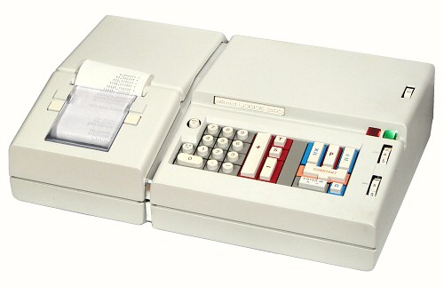
External view.
The machine is housed in a die-cast aluminium casing which measures 460W x 305D x 120H. The walls of the base section are about 5mm thick. The upper left section opens to give access to the printer ribbon and paper roll, while the right-hand section is normally held shut by a screw under the front. A polished trim strip provides a logical division between the two sections. The casing alone weighs over 4kg; the complete machine weighs just under 15kg.
The exterior of the Logos 200 series is the work of noted industrial designer Mario Bellini (1935- ), and is shown in his US patent D225533 (filed in 1970).
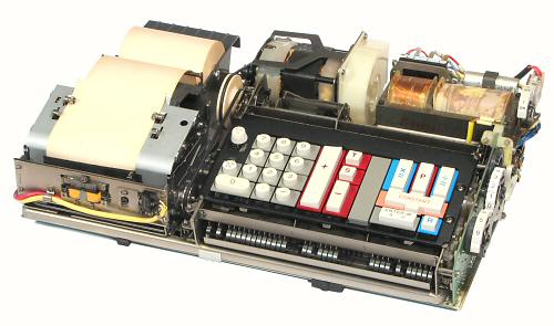 General arrangement.
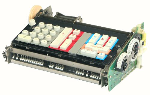
This view shows the Logos mechanism removed from the case. The printer mechanism is at the front left, and the keyboard at the right. The drive motor is at the centre rear, with the power supply at the right. The electronic circuitry is all contained on a single large board which is just visible under the baseplate.
The general arrangement of the Logos machine is a good example of modular design. Assembly and future maintenance are greatly simplified by building the machine as a series of self-contained units, each with clearly-defined functions, simple mountings, plug-and-socket wiring, and an absolute minimum of interconnections.
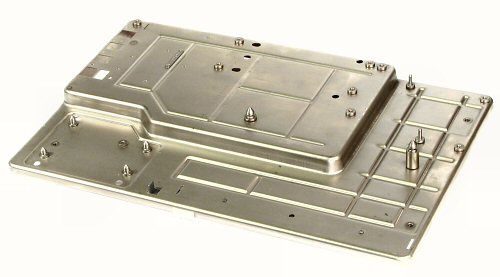 The baseplate.
The mechanism is built on a hollow pressed-metal baseplate measuring 400 x 260mm. The front section is 10mm deep, with a raised section 25mm deep at the rear. The baseplate is supported on four pillars which sit in rubber bushings in the floor of the casing.
Conical locating pins are provided for the keyboard and power supply to ensure that they mate correctly with the pin-and-socket connectors on the main circuit board.
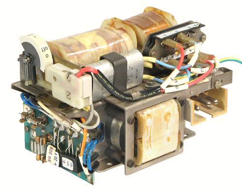 The power supply.
This view shows the power supply module from the rear. The upper section contains the On/Off switch, line filter, and the mains terminal block. The lower section contains the rectifier board, filter choke and capacitors, and the mains inlet socket. The mains connections are all fully insulated, the wires are all clearly numbered, and the rectifiers and fuses are labelled with their ratings.
The module uses a complex constant-voltage transformer to provide a regulated AC input to the rectifiers. The 5V and 20V DC outputs are filtered but otherwise unregulated, apart from a zener diode to supply the clock oscillator on the main circuit board. The DC fuses are rated at 1.25A and 0.8A respectively, for a total of only 22W output at full load. The power supply outputs are transferred to the main board via the fixed pin-and-socket connectors at the bottom left corner. The only other off-module connections are an earth wire to the casing, and two quick-connects from the terminal board to the drive motor.
 The drive motor.
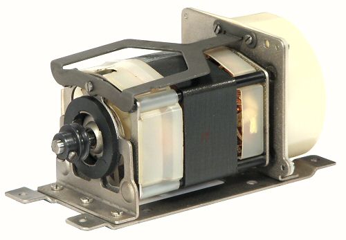
The printer and the keyboard encoding mechanism are driven by a capacitor-run induction motor mounted at the centre rear of the machine. The capacitor is mounted under the paper roll tray.
The motor is supported in rubber bushings and has a flexible earth connection. An internal axial-flow fan provides cooling for the motor, while a centrifugal exhaust fan at the right-hand end provides cooling for the case. The 50Hz motor runs at a nominal 3000RPM, and operates continuously while the machine is switched on. The motor is labelled 35W, and the machine as a whole is labelled 100W.
 Overview.
The Logos keyboard uses mechanical encoding to produce a 6-bit binary key code and a strobe pulse for each keypress. The technology is similar to that used in the Programma 101, which in turn appears to have been borrowed from Olivetti's teleprinter machines. The keyboard has a very light touch and a positive action, with a typewriter-like "clack" in response to each keypress.
The keyboard mechanism uses a set of code bars which run front to back below the keys. The bars are supported on curved leaf springs front and rear, so that they can move a short distance both horizontally and vertically. The lower edges of the bars have a set of projections according to the code to be generated. The front ends of the code bars and the forward leaf springs are visible along the lower front of the keyboard.
As a key is pressed, the corresponding code bar is pushed rearward, causing the engagement of the single-turn clutch at the left-hand rear corner. The clutch drives a cam, which presses the active code bar downwards. The projections on the bar set the positions of six rocking switch bars which run left to right under the keyboard. The switch bars control the operation of six reed switches on the circuit board at the right-hand side to produce the corresponding binary output. A mechanical escapement at the left-hand side generates the strobe pulse via another reed switch.
The basic mechanism has provision for four rows of ten keys. It was reconfigured to suit the different Logos 200 models simply by changing the keys and the corresponding code bars.
The keyboard module sits on two locating pins and two slots on the baseplate and plugs in to the main board below. There are no "off-board" connections (apart from the mechanical drive belts). The entire keyboard assembly can be removed in an instant by releasing two sliding latches at the front and rear.
 The drive mechanism.
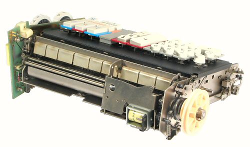
This view shows the drive mechanism at the rear of the keyboard. A single-turn clutch is located inboard of the pulley, with operating cams on both sides of the frame plate. The belt drive from the motor runs the keyboard drive shaft at about 900RPM, or 65mS per cycle.
The keyboard is normally locked by a spring-loaded bail across the centre rear. The bail blocks the movement of the code bars until it is released by the solenoid at the lower right.
There are two segmented rocking bars across the rear of the keyboard. The inner bar (hidden) is pressed rearward by the code bars to engage the clutch. The outer bar is driven by a cam to reset the code bars near the end of the cycle. Other cam-driven mechanisms lower and raise the code bars at the appropriate times.
The escapement mechanism at the right-hand front (in this view) is driven by a link from the camshaft. The escapement has two mechanical adjustments to control the timing and duration of the strobe pulse.
 The reed switches.
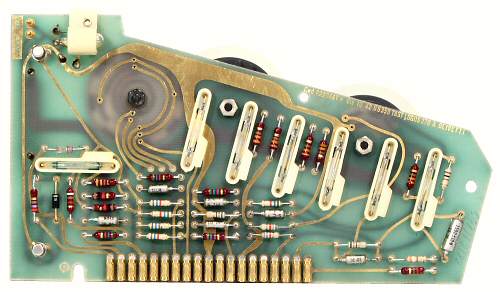
The keyboard circuit board contains the seven reed switches with their pull-up resistors and anti-bounce capacitors. A 16-position thumbwheel switch with a 4-bit binary encoder is used to set the (fixed) decimal point position. A second 3-position thumbwheel sets the round-off mode for accumulation of products. The leftmost reed switch (for the 1 bit) is arranged horizontally to make room for the encoder above.
The only active components on the board are two transistors to drive the (un)locking solenoid and an "Error" indicator lamp.
The keyboard connects to the main board via the 19 pin-and-socket connections along the lower edge.
 The coding mechanism.
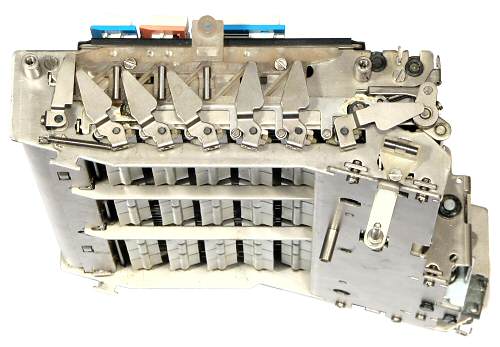
This view from the lower right-hand side shows five of the six switch bars along the underside of the keyboard. The code bars run front to back (left to right in this view) above the switch bars. As the code bars are pressed down, the projections on their lower edges rotate the switch bars left or right of horizontal. The switch bars have triangular metal blades attached to their ends, with small bar magnets mounted in a plastic holder behind. If a bar rotates left (for a 1), the blade uncovers the magnet and operates the corresponding reed switch. The code illustrated is 111001 - note that the rightmost blade (for the least-significant bit) is offset by 90°. The leftmost rectangular blade operates the last reed switch to generate the strobe pulse.
The sequence of operation is as follows:
1. Key press pushes code bar rearward, clutch engages
2. Cams unlock switch bars, press active code bar down,
re-lock switch bars
3. Escapement generates strobe pulse
4. Code bar rises and returns forward, clutch disengages
The process is completed in 65mS, for a maximum rate of 15
keystrokes per second.
The keyboard is locked via the solenoid while the circuitry is processing the keystroke. The keyboard is locked mechanically if two keys are pressed simultaneously, and is reset by a "Keyboard Clear" key on the left-hand side.
 The printer mechanism.
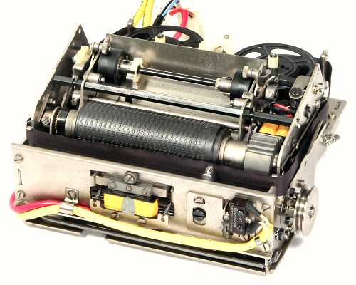
This view shows the printer mechanism with the top cover removed. The ribbon and paper feed mechanisms are at the rear, with the rotating impression roller at the front. The travelling print hammer is visible at the front right, between the front plate and the ribbon. The hammer is operated by the double solenoid at the front centre.
The steel impression roller is 30mm diameter and carries 25 columns of digits on 2.7mm centres, with 3 more columns of symbols on the right-hand side. Of the 24 rows around the circumference, 12 are used for digits 0 to 9, the decimal point, and the minus sign, 16 are used for symbols, and the remainder are blank or filled with zeroes. The paper feed advances 5mm per line (5 lines per inch) to produce a clear and well-spaced printout. The paper roll is 85-90mm wide.
The mechanism is driven by the pulley on the right-hand side, which runs continuously at about 800RPM. The impression roller is driven 2:1 by a toothed belt from the mainshaft, and runs at 1600 RPM. The toothed wheel at the right of the roller provides synchronising pulses to trigger the printing of the required digit in each column. The hammer response is critical to achieving a uniform printout, as each digit is only available at the printing position for about a millisecond.
All of the logic, timing, and driving electronics for the printer are located on the main circuit board. The only electrical components in the printer itself are the 2 synchronising coils, the hammer and clutch solenoids, and a "home" micro-switch. These connect to the main board through 5 separate 2-pin plugs, each clearly labelled and numbered.
The printer mechanism is mounted on rubber bushings on four pins on the baseplate, and is secured by a large shouldered screw and another rubber bushing. It is necessary to remove the top cover and the paper feed mechanism (4 screws into the hexagonal cross-bars) to get access to the retaining screw.
 The printer traverse mechanism.
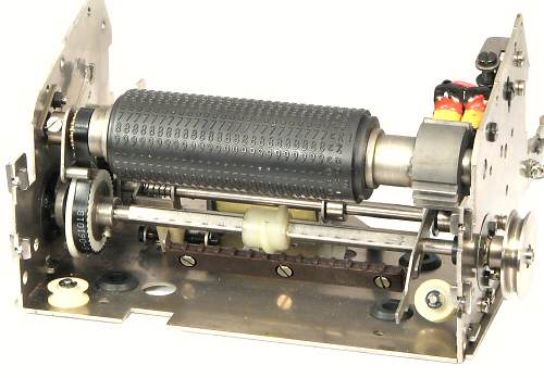
The print hammer is supported on a small carriage (removed for clarity) which surrounds the nylon worm gear under the impression roller. The worm is driven right-to-left along the square mainshaft when the toothed rack (below) is lifted into engagement. The worm is not uniform, but is shaped and timed so that the carriage pauses at each column while the 12 digit rows pass by on the roller. The worm has a pitch of 5.4mm, so that the carriage advances 2 columns for each turn of the drive shaft (as required by the 2:1 gearing). At 800RPM it takes about 1 second to print all 28 columns, or 30mS per column for shorter numbers. When printing is completed, the rack disengages and the carriage is returned to the right by a long tension spring around the two nylon pulleys. The front part of the spring is visible in the illustration above.
The printer mechanism is controlled by a solenoid at the rear and a clutch and cam mechanism to the left of the toothed belt drive. The cam raises and lowers the feed rack in response to the solenoid, and simultaneously operates the paper and ribbon feed mechanisms.
The impression roller drive uses a nylon toothed pulley moulded over a steel hub, and a polyurethane timing belt. Both of these components can be expected to have failed with age, leaving the printer (and hence the entire calculator) inoperable. Repairs can be made fairly easily using standard components.
 Overview.
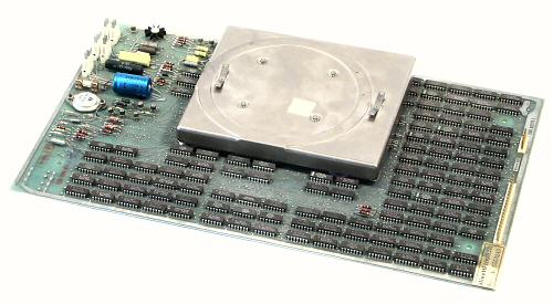
This view shows the main printed circuit board with the delay-line memory module attached. The board is mounted component side up on four pillars under the baseplate, with additional support from thick rubber strips and spring-loaded earth pads. The power supply and keyboard connect via the rows of pins along the right-hand edge. The printer connects via the pins at the right-hand rear.
 The main board.
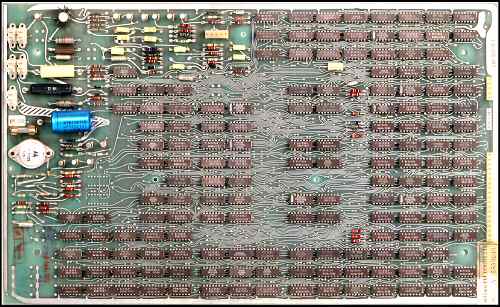
The entire electronic circuitry is contained on a large double-sided board measuring 420 x 255mm. The calculating and printing logic comprises 157 SSI (Small-Scale Integration) chips in 14-pin packages, and occupies about three-quarters of the board. There are very few discrete components among the logic chips.
The interface circuits for the printer are along the left of the board, with the clock generator and delay-line driver towards the top centre. The single-phase clock runs at 550kHz. Some of the interface circuits have been traced and are available in the Appendices below.
The logic circuits operate from the unregulated 5V supply, with a current drain of only 1.2A for the 157 chips (less than 8mA per chip). The delay line driver and the printer and keyboard solenoids operate from the +20V supply.
 Main board detail.
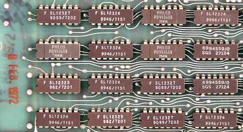
This view shows the type numbers and date codes on a typical selection of chips. The board itself is labelled "Logos 245" and has its own serial number. The three dates visible in the photo are 8 Feb 1972, 18 Mar 1972, and a hand-written 14/3.
 MOS Main board.
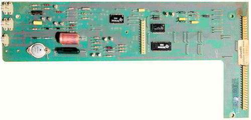
A correspondent from Argentina has sent this photograph of a MOS-LSI main board from a later Logos 270 machine. The calculator uses the same mechanical keyboard and printer, but the 157 chips and the delay line memory have been condensed into just three custom MOS-LSI chips from Texas Instruments in America. The chips are numbered TMC1827, 28, and 29, with date codes in weeks 12 and 13 of 1973. The board is labelled LOGOS 245 MOS. It replicates the functions and the electrical interfaces of the 245 SSI board above, but it is not a direct replacement due to the rearrangement of the keyboard and power supply connections. (The printer connections appear to be identical).
 The memory module.
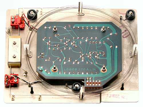
The delay line memory provides dynamic storage for the five working registers of the machine. The memory module is similar to that used in the Programma 101.
The pressed-metal housing measures 180 x 160 x 18mm, and attaches to the main board via three rubber vibration mounts. The metal housing is grounded to the machine case by spring-loaded pins through each of the rubber mounts, and by spring contacts to the main baseplate above.
The input and output transducers are at the left of the photo, with an elastomeric damping assembly between. The delay line itself is a coil of 5 turns of wire of 0.50mm diameter, supported on four grooved posts at 90° intervals. The coil diameter is 150mm, for an overall wire length of about 2.5m. The supports can accommodate more turns for models with additional storage registers.
The driver circuitry is located on the main board, while the 6-transistor sense amplifier is on the board in the centre of the module. Schematics are available in the Appendices below. Connections to the main board are made via the 5-way socket on the lower edge. The amplifier board is labelled "Logos 270" and was (presumably) common to all models. The base is stamped "Logos 240" to indicate the length of the delay line, and is dated 13 Mar 1972.
In operation, pulses of 0.5μS duration are fed into the delay line via the transducer at the lower left, and emerge about 800 μS later from the output transducer and the sense amplifier. The pulse train is regenerated or modified as required, then fed back into the module to form a continuous recirculating memory. In round figures, with a clock rate of 500kHz, a maximum of about 400 pulses or 100 BCD digits can be stored in transit in the 800μS delay line.
 Memory organisation.
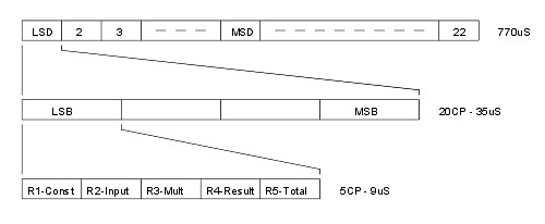
The memory cycle (top) is divided into 22 digit times (as in the Programma 101), but it appears that only 16 are available for keyboard input. The cycle begins with a single synchronising pulse, then the digits starting with the least significant (ie, the most recently entered). The earlier (more significant) digits are moved along the line as new digits are entered.
Each digit time is divided into four BCD bit times (centre), with the least-significant bit first.
Each bit time is divided into five register times of one clock pulse each (bottom). The five working registers are multiplexed into the bit times in the order shown. The presence or absence of a pulse at the corresponding time indicates a 1 or 0 respectively in that bit in that particular register. (The register names have been made up to suit myself according to their apparent usage. I do not know what Olivetti would have called them).
The clock rate is about 550 kHz or 1.8μS. Each multiplexed BCD bit time occupies 5 clock pulses or about 9μS. The four bit times for each digit occupy 20 clock pulses or 35μS, and the 22 digit times occupy 440 clock pulses for an overall cycle time of about 800μS.
 Memory example.
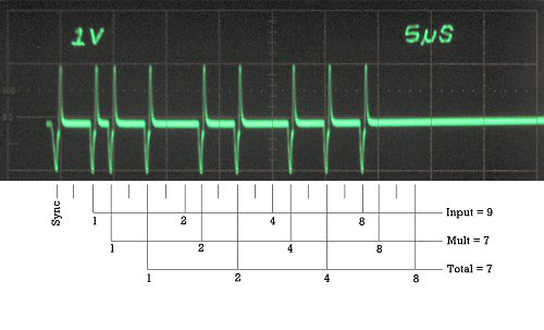
This oscillogram shows the first 45μS of the delay line signal after clearing the registers and entering 7 + 9 on the keyboard. The decimal dial is set to zero. (The waveform is the voltage across the input transducer, with the baseline at the +20V supply).
The scale below the trace shows the 20 clock pulse positions for the least-significant (and in this case, the only) digit.
The synchronising pulse which begins the memory cycle is at the left. The input register, beginning 2 pulses after the sync, has pulses in the 1 and 8 bit positions to represent the most recent input 9.
The total register, beginning at the 5th clock pulse, contains the original 7 (binary 1+2+4) which was added to the total when the Add key was pressed. At the same time, the 7 was also copied into the multiplier register and remains available for further operations.
The constant register (starting at the first clock pulse after the sync) and the multiplier result register (starting at the fourth) remain empty.
 Operator keyboard.
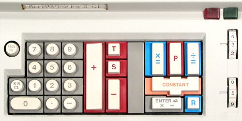
This section gives a very brief overview of the basic machine operations. The notes are based on observations only, in the absence of any official operating instructions.
The Logos 240 keyboard is divided into three separate areas for numeric entry, addition/subtraction, and mutiplication/division. The keys are coloured and shaped to indicate their logical relationships.
The machine powers up with the Power and Error lamps lit and the keyboard locked. Pressing the round Regs Clear key resets the machine and prints a confirming symbol.
The grey numeric keypad includes a Keyboard Clear key to erase an incorrect entry, and to release the error lock when two keys are pressed simultaneously.
Addition and subtraction operate in adding-machine fashion using the red keys. Each entry is printed as soon as the Add (or Subtract) key is pressed, with the result accumulating invisibly in the Total register. The S (for Sub-total) key prints the register without clearing, while T prints and clears the Total. To add 2+3 and print the result the operator presses 2 + 3 + T.
Multiplication and division operate in postfix or "reverse Polish" fashion using the blue keys. To multiply 2x3 the operator enters 2 Ent 3 Mult, and the machine prints the two factors and the result. Multiplication and division have a separate Result register which is independent of the Total register, but results can be transferred between them using the Enter and Add keys. The blue R key recalls the contents of the Result register, which contains the result of the last multiplication or the remainder from the last division (as it does in the Programma 101).
The Constant key produces no action on its own, but is shaped to indicate its use in conjunction with its four neighbours. Pressing Enter/Const together copies the Input register into the separate Constant register. Pressing Mult/Const together multiplies the keyboard input by the Constant, while Div/Const divides by the Constant.
The P key, located in the mult/div section but with a red background, is used for the accumulation of products into the Total register.
The thumbwheel switch at the upper right selects the fixed decimal point location (0 to 7 places). There are two additional red-coloured settings for 2 and 3 places for currency calculations in adding-machine mode. The front thumbwheel sets the round-off mode when accumulating products. New thumbwheel settings do not take effect until the machine is reset.
I would be grateful to any readers who could supply original technical or user instructions for the Logos 200 (or similar) machines.