 The clearing levers.
The clearing mechanism prepares the machine for a new calculation by returning the numeral wheels to zero and re-setting the mechanism to a known initial state.
The "Zero Signal" mechanism confirms that the machine has been properly cleared by providing visual, tactile, and audible signals at the start of the next operation.
The clearing levers.
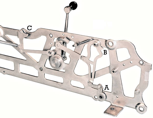
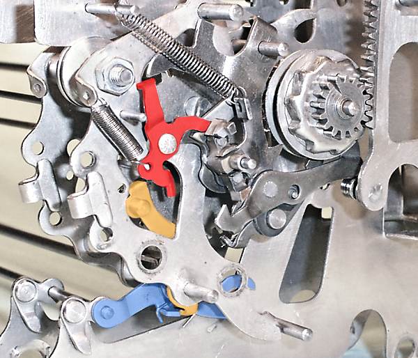
The clearing handle is mounted near the centre of the right-hand frame support plate. The handle rotates about 30° between stops on the parallel bars of the plate. A non-return pawl ensures that the handle completes its full stroke.
The clearing handle drives a series of links and levers on the inside of the support plate. The clearing levers are not attached directly to the mechanism, but operate through a series of cams in such a way that the entire support plate can be easily removed.
A rotates forward through 90°, operating the rock frame
release mechanism and allowing the numerals to return to zero.
B operates a "release plate" to clear any incomplete
operations of the trigger and accumulator interlocks.
C raises the front column lock retainer wire, releasing
the segment lever locking hooks and allowing the touch-off bar to
reset for a new operation.
A coil spring at the rear of lever C pulls the cams and levers back to their starting positions after clearing.
Later versions of Model J have an additional interlock lever which prevents the return of the clearing lever unless all of the segment levers have returned to their home positions.
Resetting the numerals.
 The rock frame.
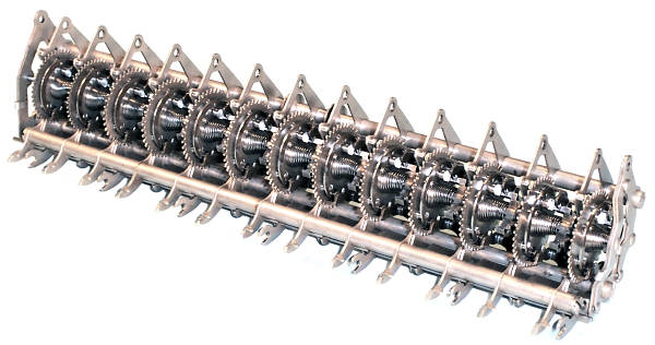
The rock frame is a major sub-assembly which houses the carry gears and the escapement mechanisms. The frame hangs from the intermediate gear shaft at the front of the machine, and rocks forward to disengage the gears and allow the numerals to return to zero.
The positioning mechanism must clamp the rock frame firmly into place during normal operation, so as to resist the reaction forces on the carry gears and the escapement wheels, but must allow the whole assembly to swing forward easily when required for clearing. Two "over-centre" or "toggle" linkages provide the necessary action.
 The rock frame toggle locked.
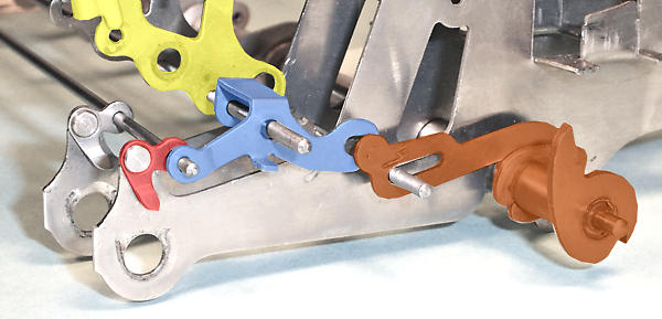
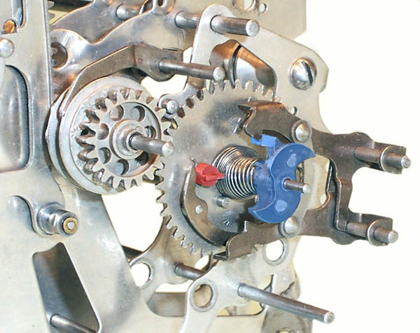
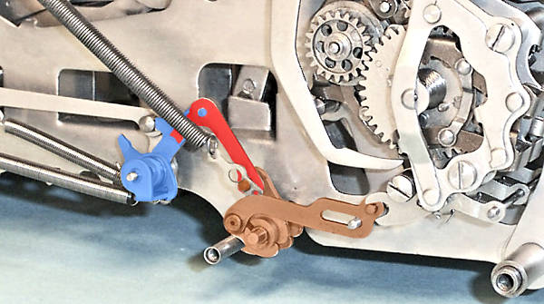
The first toggle mechanism is located under the rock frame at the front of the machine. This view from the front right-hand corner shows the mechanism with the register engaged during a calculation.
The small "L"-shaped toggle links (red) are riveted to the front of the frame plates. The links are connected via a pivot wire to the toggle levers (blue), which are mounted between the plates of the rock frame (yellow). When the pivot wire drops "over centre" to the position shown, it pushes the rock frame rearward and locks it securely in position. The lower rock frame spacer rod (not shown) acts as a stop for the rear of the toggle lever and sets the amount of over-centre travel.
The toggle linkage is repeated in every second column to ensure that the rock frame is clamped firmly across its full width.
The rock frame actuating shaft and the slotted connecting links (brown) are in their normal rest positions. The pin at the front of the connecting link is only loosely engaged with the fork at the rear of the toggle lever.
 The rock frame toggle released.
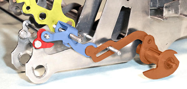
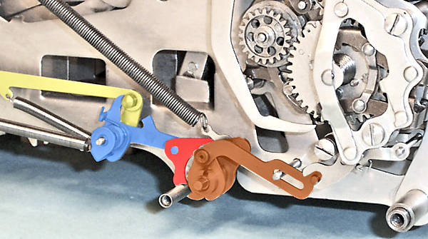
To release the toggle, the rock frame actuating shaft (brown) is rotated 90° anti-clockwise by cam A in the clearing handle linkage. The shaft has a strong return spring on the opposite side of the machine, but is held in the forward position by a second "detaining toggle" (described later) when the clearing handle is released.
As the actuating shaft rotates forward, the sloted links press forward and downward on the rear of the toggle levers, raising the pivot wire "above centre" and swinging the rock frame forward. The movement is only about 1/8" at the toggle links, and 1/16" at the carry gear. Excess travel is limited when the rearward arms on the small toggle links strike the underside of the toggle levers. The detaining toggle holds the actuating shaft, connecting links, and rock frame in the positions shown until the start of the next calculation.
When the detaining toggle is released (described later) the spring pulls the actuating shaft rapidly clockwise. The movement of the slotted links throws the rear of the toggle levers upwards, pushing the rock frame rearward and dropping the toggle links to the over-centre position (as in the previous illustration).
 Releasing the carry gear.
As the count advances, the increased tension in the carry spring is resisted at one end by the long arm of the escapement wheel pushing against the detent, and at the other end by the carry gear pushing against the accumulator gear. The accumulator gear is held fast by the backstop.
Swinging the rock frame forward releases the carry gear from the accumulator. The escapement wheel is still against the detent, so the spring tension drives the carry gear clockwise and numerals back towards zero.
The driving force ceases at the zero position when the red stop pin reaches the escapement arm, but the gear train will over-run due to inertia. The escapement wheel will be pushed back "before zero", as there is no longer any spring tension holding the arm against the detent.
A positive mechanism is needed to eliminate over-run and ensure that the carry gear and the numerals come to rest in a definite zero position. This will also ensure that the carry gear will re-engage cleanly with the accumulator when the rock frame is swung back at the start of the next calculation.
 The zero stop.
The zero stop is a short vertical arm (orange) attached to the rock frame toggle lever (blue) via a spring-and-stop arrangement in its hub. As soon as the toggle links (red) start to rise for clearing, the zero stop swings rearward into the path of the small flattened stop pins (brown) on the right-hand face of the carry gear.
When the carry gear is released, the zero stop catches one or other of the pins just before the main carry gear stop pin on the front face reaches the escapement arm. This ensures that there will always be a residual spring tension (from the pre-load) holding the gears and the escapement in definite known positions.
When the rock frame toggle drops back at the start of a new calculation, the zero stop swings forward and clear of the stop pins so that the carry gear can rotate continuously.
Resetting the interlocks.
 The release plate.
A short keystroke will trip the "Controlled Key" mechanism and lock the accumulator and segment lever in mid-stroke. The operator may repeat the keystroke and correct the error, but may also simply abandon the calculation. In this situation, the clearing mechanism must be able to release the locks and allow the segment lever to rise.
The "release plate" (brown) is a round bar with a series of rearward-facing fingers. The release plate pivots between the frame support plates, and is operated by cam B of the clearing mechanism. As the clearing handle is pulled forward, the fingers press downwards on the forks connecting the accumulator locking hook (red) to the trigger. The trigger is disarmed as it would be at the bottom of a normal keystroke, the locking hook is raised clear of the accumulator, and the segment lever rises and completes the cycle.
The Model H release plate has a second set of forward-facing fingers which lift the pinion ratchet reverse locks (blue) during clearing. The Model J does not have these fingers, although the rearward lifting tabs on the PRRL are still present.
 The accumulator latch and latch lifter.
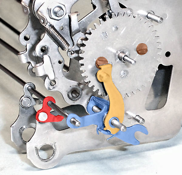
The accumulator latch (red) is an additional detent lever intended to assist the re-engagement of the carry gear by preventing the accumulator from moving out of position during clearing. Model H had a different latch design with a longer "latch release lever". The new version shown here was apparently introduced early in the Model J production, as the new parts are not mentioned in the first Model J technical manual from February 1926.
The new latch lever is mounted on the same shaft as the subtraction cutoff lever, and is spring-loaded clockwise. A tooth at the forward end of the latch is shaped to fit between the teeth of the accumulator gear.
During normal operation, a pin on the top rear of the rock frame side plate (yellow) pushes rearward on a small "latch lifter" (blue) mounted on the backstop shaft. The latch lifter raises the latch and holds it clear of the accumulator while the rock frame is engaged.
As soon as the rock frame starts to move forward for clearing, the latch drops onto the accumulator gear and stops it being "bounced" out of position by the reaction forces when the carry gear is released.
While this cures one problem it creates another, in that the latch will prevent the accumulator from advancing if it is necessary to clear an abandoned calculation. To solve this problem, the latch lever is provided with a rearward vertical extension. The tip of the extension (shown yellow in the photo above) is also pressed down by the release plate, thus lifting the latch and allowing the accumulator to advance. (The numerals will not advance, since they are already at zero and disconnected from the accumulator). When clearing is completed, the latch will drop back between the teeth of the accumulator gear to position it for re-engagement.
 The zero stop and locking dog.
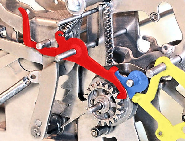
This view shows the rock frame toggle lever (blue) and zero stop (orange) assembled between two rock frame side plates. With the rock frame toggle engaged, the zero stop is held forward and clear of the carry gear stop pins.
When the rock frame toggle is raised for clearing, the toggle lever rotates the zero stop rearward. The pin near the top of the zero stop will strike the lower arm of the carry lever locking dog, rotating it anti-clockwise. The upper arm will move out from under the carry lever, and the rearward arm will be lifted clear of the escapement wheel.
While there are more than a few complications involved in clearing incomplete keystrokes and possible delayed carries, it is not at all obvious why this particular interlock should be necessary. Suggestions from readers would be welcome.
The Detaining Toggle and the Zero Signal.
 The rock frame detaining toggle.
The rock frame detaining toggle consists of a pair of short levers mounted in the leftmost or "overflow" column. (The column has an accumulator and a modified carry mechanism, but no keys or segment lever). The rear lever (blue) is in two parts which are connected by a stiff torsion spring and usually move as one. The assembly is mounted on a short axle between the two leftmost frame plates. The front lever (red) is connected to the operating pin on the rock frame actuating shaft.
The illustration shows the rock frame engaged and the detaining toggle linkage raised. The large coil spring at the top left holds the actuating shaft rearwards.
 The detaining toggle engaged.
As the clearing handle is drawn forward the rock frame actuating shaft rotates 90° clockwise to the position shown. The detaining toggle drops over-centre (assisted by the lower rear spring) until the downward arm of the red lever comes to a stop against the lower frame tie rod. The clearing lever and cam return to their rest positions, leaving the actuating shaft and the rock frame "detained" in the forward position.
The rock frame is pivoted on the same shaft as the intermediate gear. As the frame rotates forward, the intermediate gear rotates a corresponding distance in the same direction (as the carry gear is held fast by the zero stop). The numeral wheels rotate the same distance backwards, leaving the zero numerals slightly (but definitely) offset in the viewing windows. This provides a visual signal that the machine is clear and ready for use.
The detaining toggle is released by pulling rearwards on the release link (yellow), which raises the toggle links above centre via the bell crank at the rear pivot. The actuating shaft spring then pulls the mechanism back to the position in the previous view.
 The detaining toggle release bar and bell hammer.
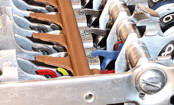
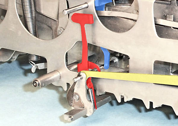
The detaining toggle release bar is another 1/8" x 1/4" bar pivoted between the frame support plates near the bottom rear of the machine. A round wire of 0.088" diameter is supported above the bar on a series of fixed arms, and is connected to the rear end of the detaining toggle release link.
A spring near the detaining toggle holds the release link forward, which holds the wire against the tails of the brake levers (blue) in every column.
When any key is pressed, the segment lever roller pushes the corresponding brake lever rearwards. On the first key press after clearing, the brake will push the release bar rearward, pulling on the release link and raising the detaining toggle. A firmer key pressure is required to break the toggle (against the tension of the actuating shaft spring), providing a tactile signal that the machine has started from clear.
As the detaining toggle rises, it pushes the release link sharply rearward, throwing the spring-loaded hammer (red) momentarily against the bell. The bell is attached to the left-hand support plate, adjacent to the large round cutout, and provides the third (audible) zero signal.