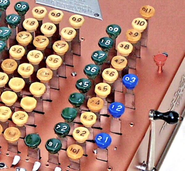
 The Sterling keyboard.
In a decimal Comptometer, every column operates on a cycle of ten counts for a full rotation of the numeral wheel.
For non-decimal machines, there were sets of gears and springs available to provide cycles of 2, 4, 6, 8, 10, 12, 16, 20, 40, and 60 counts.
This page describes the main differences in the mechanism of the Sterling-currency machines.
The Sterling keyboard.
Looking from the right-hand side, the key columns on a Sterling Comptometer are:
Shillings are actually base-20, but are separated into tens and units in most mechanical calculators.
Farthings were never issued as Australian currency, but half-pence or ha'pennys (ie, 2 farthings) were still in use until the 1950s. If accounting for ha'pennys was not required, the farthings column was sometimes deleted in favour of an additional pounds column.
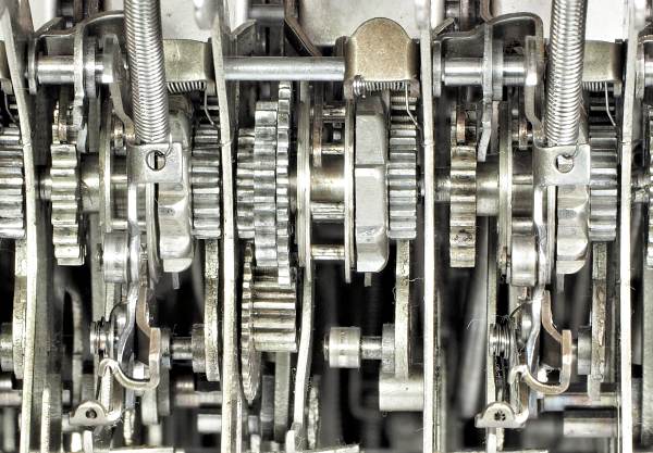
 The gear train revisited.
It would be well to review the features of the decimal gear train before considering the differences in the Sterling columns.
The pence column.
The pence column (base-12) has 12 steps on the ratchet and lantern wheel, and 12 digits (0 to 11) around the numeral wheel.
There are two additional keys located behind the 9 key, with additional operating tabs on the segment and lock levers and the key stop levers. The sawtooth rack has 6 levels, and the key stop levers are set to advance the accumulator in twelve 30° steps.
The only complication is that the accumulator gear must have an integral multiple of 12 teeth to allow the latch to operate correctly, so the 20-tooth decimal gear can not be used. The accumulator gear is given 24 teeth (2 teeth per step), which means that the numeral wheel must have 24 teeth and the carry gear 48. All of the gears are cut to a finer pitch to keep the same diameters as the decimal gears. (All of the columns use the same shafts and centres, regardless of the number base).
The farthings column.
The farthings column (base-4) is actually base-8, with a 2-times multiplier provided in the keyboard layout.
The ratchet and lantern wheel have 8 steps, and there are 4 steps on the keystop sawtooth rack. The key stop levers are set to advance the accumulator in eight 45° steps. However, the numeral wheel has only 4 digits (0 to 3) at 90° spacing, with blank positions in between. (Some farthings numeral wheels are actually marked in eighths).
The keys for 1, 2, and 3 farthings are located in rows 2, 4, and 6, so that each key advances the accumulator by twice as many places. The "odd" keystops are never used in the farthings column, but still need to be installed to help retain their neighbours.
The accumulator gear must have an integral multiple of 8 teeth, so it uses the same 24/48-tooth gears as the pence column (but with 3 teeth per step rather than 2).
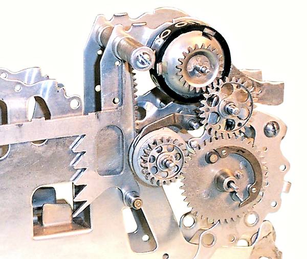
The ten-shilling column.
The ten-shilling column (base-2) is also derived from base-8, with a 4-times multiplier provided by a set of auxilliary gears on the accumulator.
The illustration shows the accumulator for the ten-shilling column (centre), with decimal columns either side. The carry lever has been removed for clarity.
The ratchet and lantern wheel have 8 steps, as for the farthings column. The numeral wheel is marked only with 0 and 1, 180° apart, and must rotate half a turn at a time. The key stops and key stop levers are not required, as the column only ever moves to the "1" position. The levers are deleted and replaced with a single fixed stop attached to the frame plate (visible below the segment lever roller). A short auxilliary lever (not shown) is used to disarm the trigger at the bottom of the keystroke.
The accumulator gear is normally attached directly to the lantern wheel, with a short space on either side (as in the decimal columns shown). The right-hand space is normally occupied by the latch lifter, but in the ten-shilling accumulator it is used for a narrow 32-tooth gear. This gear is attached to the lantern wheel (in place of the accumulator gear), and drives a 16-tooth auxilliary gear mounted on the frame plate. The auxilliary gear is attached to a 32-tooth gear on its left, which drives another 16-tooth gear back on the accumulator shaft. This gear is attached to the "real" accumulator gear, which is in its normal position on the shaft. The two cascaded 32:16 ratios will drive the accumulator gear at 4 times the speed of the lantern wheel.
One step on the lantern wheel (1/8 of a turn) will be multiplied to 1/2 a turn on the accumulator gear, or 2 steps for a full cycle. The accumulator gear can have any even number of teeth (as it rotates exactly half a turn at a time), so it is given 20 teeth to use the standard decimal gear train.
The accumulator latch has to be redesigned, as the space previously used by the latch lifter is now occupied by the auxilliary gearing. The new latch is mounted on the intermediate gear shaft in column 5, and passes through the frame plate to engage with the accumulator.
The additional gearing results in greater inertia and greater free play in the gear train, which leads to several more minor modifications. The segment lever springs are made stronger, and the carry spring in the preceeding column is given increased pre-load. An interlock is provided between the segment lever and the rock frame toggle actuating shaft to ensure that any incomplete keystrokes are resolved manually before the machine can be cleared.