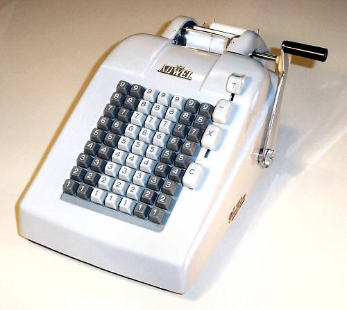
 Adwel Model W504, S/N 799113
Functions: Add, subtract, sub-total, total; manual operation
Digits: 7 keyboard, 8 printer
Dimensions: 8-1/2"W x 14-1/2"D x 6-1/2"H
Weight: 15 pounds approx
Manufactured: Bergen, Norway, c.1960.

|

|
|
Adwel Model W504, S/N 799113
Functions: Add, subtract, sub-total, total; manual operation Digits: 7 keyboard, 8 printer Dimensions: 8-1/2"W x 14-1/2"D x 6-1/2"H Weight: 15 pounds approx Manufactured: Bergen, Norway, c.1960. |
|
Adwel founder Jörgen S Lien (b.1909) was involved with the office machine industry from 1931. By the late 1950s his factory in Bergen (Norway) was exporting Regna cash registers and Adwel adding machines to 75 countries. The firm did not survive the transition to electronics and closed in the 1970s.
This Adwel W504 is a basic full-keyboard office adding machine for decimal currency. The hand cranked mechanism also performs direct subtraction, but with negative totals shown as complements. There is no "non-add" function. The machine contains a mechanism to suppress leading zeros in the printout, but requires the operator to make a "blank stroke" before taking a total or sub-total. Although it is a relatively simple machine, its internal mechanism contains well over one thousand manufactured parts.
The principles of operation of the Adwel machine are common to most office adding and listing machines, and may be used as a general guide to the workings of machines of similar construction.
At the most basic level, the mechanism operates on a reciprocating cycle, controlled by the forward and return strokes of the operating handle:
The construction and operation of the Adwel machine is described in more detail in the sections following.
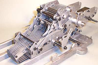
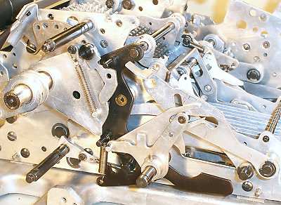
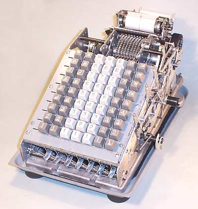 Overview with covers removed.
The calculator mechanism is mounted in a pressed-metal base pan and has a substantial plastic cover.
The keyboard has provision for eight columns, but only seven are fitted to this model. There are no Zero keys. The accumulator register is just visible behind the keyboard, in front of the rotor discs on the horizontal mainshaft. Behind the rotor is the printer platen and the paper and ribbon feed mechanisms.
There are only four operator controls (apart from the handle), located along the right-hand side:
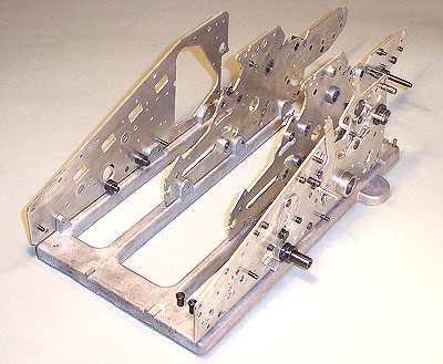 The base and side plates.
The mechanism is built on a die-cast base about 165 x 285 x 12mm thick (6-1/2" x 11" x 1/2"). There are four vertical side plates of 2.2mm (0.084") steel. The outer side plates have many redundant punchings, and are clearly intended for use on a range of models. The mechanism is quite solidly constructed, with the base and side plates alone weighing over 3 pounds.
The add-and-carry mechanism is located between the innermost side plates. The register control mechanism is on the left-hand side, and the operator controls and interlocks are on the right.
Although of European origin, the machine is a peculiar mixture of metric and Imperial dimensions. The mainshaft is precisely 10mm diameter, several other shafts are 5mm, but others are just as definitely 1/4". Many of the screws appear to be 1/8" Whitworth.
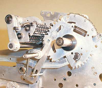
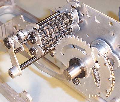 The accumulator register and the rotor discs.
This view from the right-hand rear of the machine shows the register and one rotor disc partially assembled on the inner left-hand side plate.
Each rotor disc consists of two separate sectors which are free to rotate about the mainshaft. The two sectors are held in a fixed relationship by a tension spring and stop tab, and normally move together. The rear sector is connected to the keyboard through the sliding horizontal link at the bottom, and carries the "type bar" with raised numerals for printing. The numerals include fixed decimal points (2 places) and thousands separators. The "rotor" discs only rotate up to about 90°, according to the number to be printed.
The "complementary" register consists of two sets of eight permanently-meshed 10-tooth gears mounted in a hinged frame. The upper gearset holds the positive total; the lower set therefore holds the complement, and also acts as an intermediate (ie, reversing) gear during subtraction. Each gear has a wide tooth at the Zero position to operate the carry mechanism.
The register assembly is moved rearwards to engage with the front sector of the rotor discs by a control mechanism between the left-hand side plates. It is raised or lowered to select the positive or negative gearset by a mechanism connected to the Minus key.
The add and carry cycle and its variants are described in more detail in the Operation section.
 The carry levers and links.
The register is shown here in its normal (lower) position. When moved rearward by the control mechanism, the positive gearset will engage with the front sector of the rotor disc.
The carry mechanism for each digit consists of a short sensing lever (pivoted on the central shaft) and a longer sliding link. The link is held by a flanged pin at its upper end, which passes loosely through the curved slot in the front rotor sector, and by a straight slot and fixed pin at the lower end. The sensing lever and the sliding link are spring-loaded forward and upward by a single tension spring, but the link is latched and prevented from rising by a projection under the top of the sensing lever.
During an addition cycle, the rotor discs rotate clockwise as the mechanism returns towards its home position. The register is engaged and the positive gears rotate counter-clockwise. One digit before the home position, the end of the curved slot in the front sector meets the pin on the carry link. The link is restrained by the tab on the carry lever, and so movement of the front sector stops. As the handle movement continues, the rear sector is pulled one place further, against the tension of the spring between the sectors.
If a digit passes from 9 to 0 during the return stroke, the wide tooth on the accumulator gear will press on a ramp on the carry sense lever. The lever will move rearward, releasing the latch on the sliding link on the next digit. The link will rise until stopped by the straight slot and pin at the bottom, a distance equivalent to one tooth on the sector.
As the mechanism returns to its home position, any sectors with carries pending will be able to travel one step further than those without, and will thus add one extra digit to the next register position.
 The horizontal key links.
This view of the completed addition unit shows the front ends of the horizontal key links and their return springs.
The keylinks are supported by a slotted guide plate, and are held under constant rearward tension by the long coil springs in the base of the machine.
The links are restrained from moving rearward by a bail or rod which travels horizontally in the slots near the front of the side plates. The bail is connected through the curved links to arms on either side of the mainshaft. On the forward stroke, the bail moves rearward, and the key links follow under spring tension until stopped by the keyboard.
 The keyboard transfer links.
Between the underside of the keyboard and the horizontal keylinks is a second set of sliding links, supported on two horizontal cross rails between the outer side plates. Adapter plates connect these links across and down to the pins on the fronts of the corresponding keylinks (shown in previous illustration). Each pair of links then moves as a unit, with the adapter plates simply matching the spacing of the keyboard columns (11/16") to that of the addition mechanism (5mm).
The tags along each side of the sliding links interact with tags on the bottoms of the key stems to limit the travel of the keylinks on the forward stroke. Note that pressing a numeral key does not cause any immediate action in the body of the machine. The key simply acts as a stop to limit the rearward motion of the corresponding keylink, thus setting the position to which the numeral sector can rise.
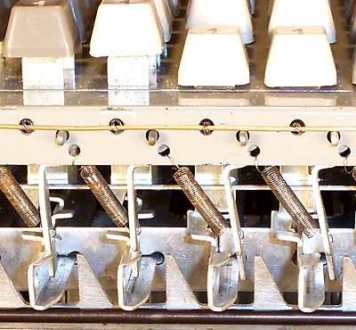 The keyboard locking bars.
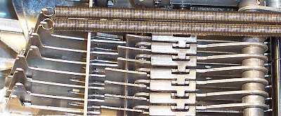
This detail view from the front of the machine shows four key columns, with their key stems and sliding transfer links. The holes along the front face of the keyboard contain the ends of the longitudinal key springs (secured by a brass wire), and the end pivots and tension springs for the column locking bars.
The two columns to the left are at Zero with no keys pressed. The extensions on the front of the locking bars stand vertically, preventing the sliding links moving rearward. The other two columns are shown with the 1 keys down. The locking bar is pushed to the right, allowing the link to move rearward until the first of the sideways tags contacts the tag on the lowered key stem.
The "sawtooth" bar at the bottom pivots rearwards during the machine cycle, blocking the movement of the locking bars and preventing further keyboard entries. Another bar at the rear of the keyboard releases all the column locking bars at the end of the machine cycle.
 The register control mechanism.
This view shows the register control mechanism on the inner left-hand side plate.
The black vertical lever pivots about its centre to move the register assembly in and out of engagement with the rotor. The vertical lever is latched in either position by the black horizontal detent lever near the base.
The movement of the vertical lever is controlled by the mainshaft, via the 60° sector and the spring-loaded pawl at its top corner. The notch in the upper surface of the pawl pushes forward on a pin near the top of the lever to disengage the register at the start of the forward stroke. A similar notch under the pawl presses forward on the lower pin to re-engage the register at the start of the return stroke.
The three interconnected levers in front of the vertical lever modify the forward and return operations on total and sub-total cycles.
The details of the register and its control mechanism differ greatly between machines and manufacturers, but the principles and the basic operations are similar.
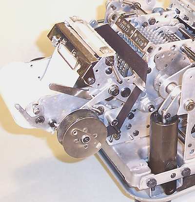 The printer and oil damper.
This view from the left-hand rear corner shows the printer mechanism with paper and ribbon installed and the platen roller in its normal (rearward) position. The roller travels forward about 1" to press the paper against the ribbon and the raised numerals. The long travel allows the operator a clear view of the printed result.
The mechanism prints 6 lines per inch on a paper roll 2-1/4" wide, but the character spacing is 5mm. The ribbon is 1/2" wide, but the shaft for the ribbon spool is 8mm.
The vertical black cylinder in the foreground is a double-acting oil-filled damper, which slows the movement of the mainshaft in both directions. The damper prevents damage to the mechanism if the operator lets go of the handle on the (spring-assisted) return stroke.
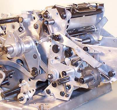 The printer mechanism.
This view from the right-hand side shows the details of the printer mechanism with the platen roller at its maximum forward stroke.
The platen roller assembly pivots on a central shaft, and is moved fore and aft by links to the arms on either side of the mainshaft. The links are fitted with eccentric bushings (in the large hex nuts) to adjust the force of the impression. A large coil spring in the shaft of the operating handle absorbs any over-travel at the end of the stroke, and limits the force that can be applied.
The paper feed, ribbon feed, and ribbon reversing mechanisms are all driven by the fore and aft motion of the platen assembly.
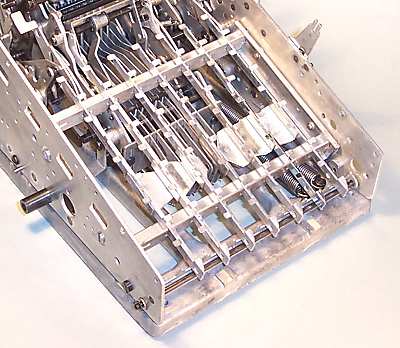
 The mechanism from underneath.
This view shows the central part of the Adwel mechanism from underneath.
The upper section of the baseplate holds the two main springs, which supply the energy for the return stroke.
The fronts of the keylinks are visible at the left of the central section, with only two of their long tension springs installed. The leading zero supression mechanism is in the centre, with the bottoms of the carry links and their reset bail visible at the right quarter.
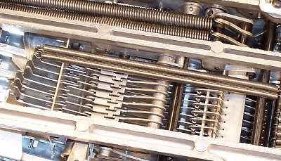
 The leading zero mechanism.
The leading zero supression mechanism consists of a set of flat-topped cascaded levers which sit between and over the keylinks (relative to this view). If all digits to the left stand at zero, the levers will drop behind a small step in the keylink; otherwise, they will have no effect.
Just before printing occurs, the shaft carrying the levers is pushed forward horizontally by a distance of one numeral position (to the left in this view). The links that are still at zero (the bottom four in the picture) will be pushed forward against their springs, pulling the numeral sectors on the rotor into a non-printing position below Zero.
These notes give more detail of the internal operation of the Adwel machine during its various operating cycles. "Forward" and "return" strokes refer to the movement of the operating handle. Angular measurements are given to the nearest 5°, and refer to the position of the mainshaft (the rotor shaft). The position of the operating handle is similar, but does not follow exactly because of the intermediate linkage.
Assume that the addition cycle starts from the "clear" state following a Total cycle. The operator enters a number on the keyboard and pulls the handle forward. A non-return pawl on the LHS of the mainshaft ensures that the machine can not be short-cycled before completing its full stroke. The non-return pawl operates on both forward and return strokes.
The register control mechanism on the LHS moves the register forward, disengaging it from the front rotor sectors at 10°. A spring-loaded locking rod prevents the register gears moving while disengaged.
As the keylink bail moves rearward, it allows the saw-tooth bar across the bottom front of machine to rotate rearward into the path of the key column locking levers (via a spring-loaded sliding link on the inside of the outer LH side plate). This saw-tooth bar stops the key column locking levers from moving sideways, thus preventing any further keyboard operation once the mainshaft has passed 30°.
There are no Zero keys, so the links in Zero columns are stopped by the extensions on the key column locking levers at 30°.
As the handle is pulled further forward, the keylinks continue rearward, raising the corresponding rotor disks into their positions for printing. At the same time, the leading-zero supression mechanism moves forward, lowering the leftmost Zero disks into a non-printing position below Zero. The transfer from keyboard to rotor is completed when the links in Nines columns reach their stops at 75°.
From 80° to 90°, a locking bail rises against the lower rear set of rotor teeth, so as to hold the numerals firmly in alignment during printing. The locking bail is operated from a slotted cam on the mainshaft, on the inside of the inner LH side plate.
The platen roller contacts the paper at 90°, and the forward stroke completes at 95° when the non-return pawl disengages.
At the start of the return stroke, the register control mechanism pushes the register rearward, engaging it with the front rotor sector at 85°.
The keylink bail picks up the keylinks at 75° and pushes them forward, pulling the rotor disks back down towards zero. As the rotor disks return, the register gears advance (CCW from RHS) by the same number of positions.
At 45°, the outermost snail cam on the RHS of the mainshaft starts to push rearward on a long horizontal sliding link on the outside of the RH side plate. The forward end of this link operates the clearing bar at the top rear of the keyboard (through several intermediate levers), releasing the keyboard locking bars and the keystems at 15°. The sliding link resets at 5°, and the cycle ends when the non-return pawl disengages at 0°.
The register remains engaged with the rotor discs at the completion of the cycle.
Note that the leftmost disk on the rotor has no corresponding keyboard column, but functions only to accumulate carries into the 100,000 place. A stop prevents this keylink moving during the addition cycles. The rightmost disk on the rotor is a symbol disk which prints a single character to indicate the operation performed.
The carry mechanism was ignored in the previous section in order to simplify the description of the basic operation.
Each rotor disc consists of two separate sectors which are free to rotate about the mainshaft. The two sectors are held in a fixed relationship by a tension spring and stop tab, and normally move together. The rear sector is connected to the sliding horizontal keylink, and carries the "type bar" with raised numerals for printing. The front sector engages with the register and the carry mechanism. The two sectors can rotate relative to each other (against the tension of the spring) by a distance of about 1.5 teeth.
Consider the situation as the keylinks are pushed towards Zero on the return stroke (with no carries pending). The rotor disk rotates clockwise as a unit until the slot in the front sector is stopped by the pin on the carry link at 30°. The keylink bail continues pushing until 10°, rotating the rear sectors about 1.5 teeth further against the tension of the sector connecting springs. If there are no carries, this excess motion will be recovered at the start of the next addition cycle and will have no overall effect.
If a carry occurs as the register is incremented on the return stroke, the wide tooth at the Zero position on the register will press on the ramp on the corresponding carry sense lever. The lever will move rearward, allowing the carry link for the next digit to rise by a distance of exactly one tooth.
Nothing further happens until the mainshaft returns past 30°, when the raised carry link allows the rotor disk to rotate one tooth further than before, thus advancing the register by one additional position.
If successive register positions to the left also stand at 9, the next carry sense lever will trip when the register has advanced by about half of the additional tooth. At this stage, the mainshaft is at 25° and has started tensioning the rotor sector springs. As soon as the carry link is released, the sector spring will pull the front sector clockwise, advancing the register and triggering an immediate ripple carry across the machine.
The cycle ends with the carry links still raised and the sector springs released on those columns where a carry has occurred.
The carry links and the sense levers are reset on the forward stroke of the next addition cycle by a clearing bail, which is operated via an over-centre lever assembly from the keylink bail. The clearing bail begins to push the carry links downwards from 35°, allowing the carry sense levers to reset at 50°. The bail reaches maximum stroke at 70° and releases fully at 85°, ready for the carry mechanism to operate on the return stroke.
Pressing the "Minus" key reverses the direction of rotation of the positive register by driving it through the lower set of gears. Otherwise, the subtraction cycle is the same as addition.
The Minus key is held down by a latch on the outer right-hand side. Interlocks ensure that it can only be pressed when the machine is idle, and can not be released until the cycle is completed.
Pressing the key tensions a spring in a lever assembly located between the two RH side plates. The spring attempts to raise the register assembly, but is unable to do so while the upper register is still engaged with the front rotor sectors.
When the register is fully disengaged at 25° on the forward stroke, the spring raises the register assembly into the upper position. On the return stroke, the lower register gears will engage with the front rotor sectors, and the upper (positive) gears will rotate in the opposite direction. The carry teeth on the lower register are displaced by an appropriate amount from the upper, but otherwise operate as previously described.
The sliding clearing link on the outer RHS releases the minus key latch at 15°. A small spring which appears to relate only to the symbol disk stop is important in returning the lever assembly to its home position clear of the interlocks.
The minus cycle ends with the register assembly still in the raised position and engaged with the front rotor sector. It will drop by gravity when fully disengaged at 25° on the next addition cycle.
To initiate a sub-total cycle, the "S/T" key is drawn forward until it latches. This holds the keyboard clearing bar in the operated position, ensuring that the keystems and zero tags are clear of the keylinks. It raises a stop from the leftmost keylink, allowing the eighth rotor disk to operate. It also acts on the register control mechanism to inhibit the initial forward motion that disengages the register. An interlock lever on the inside of the outer RH side plate prevents the key operating if Minus is selected. A second interlock holds the key firmly in position from about 10° while the cycle is in progress.
On the forward stroke, the upper register remains engaged with the front rotor sectors.The spring-loaded keylinks follow the keylink bail rearward, allowing the numerals to rise while driving the register gears in the reverse direction (clockwise from the right-hand side). The motion stops when the wide carry teeth at the zero position strike the flat tops of the carry sense levers. At this stage, the register contents have been transferred to the rotor and the register stands at zero.
The rotor contents are then printed, and the operation is reversed on the return stroke. The S/T key latch and interlocks are released at the end of the stroke.
To initiate a Total & Clear cycle, the S/T key is pressed rearward as the handle is pulled. The key does not latch immediately, but is held securely by the internal interlock once the mainshaft passes 5°.
The forward stroke begins as for sub-total, with the register contents being transferred to the rotor. But at the 90° point, a lowered tag on the register control mechanism is struck by an extension on the left of the keylink bail. The register is pushed forward and disengaged from the rotor, and its contents, which stand at zero, are secured by the spring-loaded locking rod. The rotor disks are prevented from moving by the rear sector locking bail, which has risen in preparation for printing.
On the return stroke, the sector locking bar retracts after printing is completed. There is now nothing holding the rotor or the key links, so the links spring fully rearward, raising the numeral sectors. The keylink bail then returns the links to the home position. At about 10° the register control mechanism re-engages the registers in preparation for the next cycle.
This machine always takes its totals and sub-totals from the upper register. If the total is negative, the printout will be in complement form.
To convert a complement to its normal representation, the operator would clear the machine, enter the complement on the keyboard, subtract once, and print the result. A spurious 9 remains at the left-hand side, because the keyboard has one less column than the register.
For comparison, "true negative" totals were available on more expensive machines of this general style. The extraction of the negative total or "credit balance" from the complementary register is actually quite a difficult mechanical problem, involving circular carries and the injection of a "fugitive one" as the register passes through zero.
The description of the total cycles has been simplified by ignoring the fact that the carry mechanism is not reset until late in the forward stroke of the following machine cycle.
In columns where a carry has occurred, the carry links and sector springs will still be in the released state at the beginning of the next cycle. There will be a difference of one tooth position between the numeral sectors and the register sectors, compared to a column which did not have a carry.
If a total or sub-total cycle is attempted at this stage, the register will immediately begin transferring its contents to the rotor disks. The columns where a carry had occurred will be offset by one tooth relative to the others, and will print one digit less than required.
The simplest solution to this problem is to require the operator to reset the carries by making an additional "blank stroke" or "add zero" cycle before the machine will allow a total or sub-total to be performed.
An interlock lever on the inside of the outer RH side plate normally sits over a pin on the inside of the S/T lever and prevents it moving. The interlock is released at the beginning of each cycle by a cam on the mainshaft, but is immediately tripped again if any rotor digit advances beyond zero. The trip is implemented by the extended teeth on the rear sectors pushing rearward on a hinged trip bail located below and behind the rotor. Thus the only time that the S/T key can be operated is immediately following an add cycle in which all the keyboard columns stand at Zero - ie, the "blank stroke".
A separate mechanism operated from the S/T key disables the carry reset function in both Total and Sub-Total cycles, so as not to disturb the carry levers while they are acting as stops for the register gears.
For comparison, more expensive machines reset the carry mechanism during the current stroke or early in the next, with no requirement for additional dummy operations.