John Wolff's Web Museum
Rebuilding the PLUS Rapid Adder
Contents
|
|
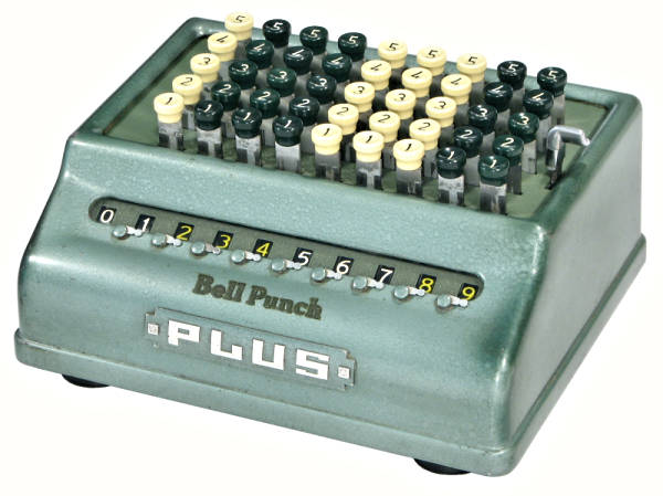
| PLUS Model 509, 1960s |
Introduction
The notes following give a detailed step-by-step procedure for a
complete disassembly and reassembly of the PLUS mechanical calculator.
The description applies to all PLUS models except the bakelite-cased
machines from 1934-38. The calculating mechanism is basically identical
throughout the rest of the range, although there are many minor
differences found in the casework and in the details of some of the
individual parts. Variations are noted where significant.
The notes have been prepared and refined during the
rebuilding of a number of PLUS machines, and may provide a useful
guide to anyone faced with a similar task. The sequence of operations
described works well for me, but comes with no guarantees as to its
efficiency or appropriateness. No responsibility will be taken for any
consequences arising from the use of these notes by others.
The notes are intended to be read in conjunction with the Technical
Description on the
PLUS page, and with the more general
information in the
Notes on overhauling a mechanical
calculator. The Technical Description explains the operation of the
PLUS mechanism and illustrates all of the major components and
assemblies, while the Notes on Overhaul describe more general
techniques for disassembly, cleaning, and rebuilding. Please study
this material before commencing your overhaul, and refer frequently
as you proceed. It is suggested that you print a copy of the
instructions following and tick off each step as it is completed.
If you find these notes useful (or otherwise) in rebuilding a PLUS
machine, I would be interested to receive your feedback, comments, or
suggestions for improvement via the
enquiry form.
Disassembly
- Preliminaries
- Disassembly involves removing the mechanism from the case,
removing the clearing mechanism, disassembling the register and carry
mechanism at the front of the machine, and then disassembling the
actuator mechanism and the frame.
- It is not necessary to keep the parts in column order. All of the
parts in each column are identical and interchangeable, with only
a few items being adjusted to suit the particular column. It is
generally much quicker to do a full adjustment on completion than
to try to keep the parts in order during disassembly and cleaning.
- A 9-column machine can be completely disassembled in an orderly
fashion in less than an hour, provided that none of the pivot wires
are seriously stuck. A difficult machine may take a couple of days.
(There is a somewhat less orderly method which takes only a couple
of minutes. It involves removing 4 nuts, placing the mechanism in a
bucket, and pulling out all the wires and tie rods. This method is
not recommended until you become thoroughly familiar with the parts
and their locations).
- Removing the mechanism
- Remove the clearing handle. Invert the machine, support the cover
on two suitable blocks so that the keys are clear of the bench, and
remove the four screws in the corners. (If you rest the machine on the
keytops, the cover will drop sideways and may damage the screw threads
in the alloy casting). Hold the base and cover together, stand the
machine back onto its feet, and lift off the top cover.
- (Early models) Lift out the slotted plates from between the keys.
- (Late models) Remove the spring-wire retainers and felt strips
between the keys. Hold each retainer as you pull out the locking wire
at the centre rear, so that it can not fly forward.
- Remove the mechanism from the base. Early models have four screws,
cup washers, and rubber bushings from underneath. In later models
(with the die-cast base) the mechanism sits loosely in four rubber
mounting blocks, which have usually decomposed and turned to jelly.
Carefully separate the mechanism from the base and remove the residues.
- Set the base, cover, and keyplates aside for cleaning and repair.
- Freeing the pivot wires
-
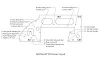 Print the larger
version of the frame layout drawing opposite (PDF file, A4, 20kb)
to show the location of the pivot wires and tie rods.
Print the larger
version of the frame layout drawing opposite (PDF file, A4, 20kb)
to show the location of the pivot wires and tie rods.
- On late-model machines, loosen the two screwed collars at the
left-hand end of wire 10 (between the leftmost frame plates).
- Press each of the pivot wires firmly from side to side with a
suitable wooden implement and check that it is free to move.
- If any wires are stuck, apply solvent to the pivot or bearing
points and work the parts carefully until they come free. This may
take a considerable time if the machine is in poor condition. Continue
until all the wires can be pushed back and forth by hand.
- If you need to use a little more persuasion on any of the wires,
use it on one end only, so that you still have a smooth end to draw out
through the bearings. Repair the damage before reassembly. If the
damage is significant, a replacement wire can be made from 1/16" or
3/32" silver steel or "music wire" rod from a model supply shop.
- You may find that the machine will work (after a fashion) when the
wires are free. Do not be tempted to quit now and declare it
finished - it will probably sieze up again by tomorrow.
- On the other hand, if the keys are still stiff or blocked when
the pivot wires are free, it indicates that there are siezed joints
in the linkages themselves. Do not force or attempt to free the keys
at this stage, or you may cause significant damage by loosening the
rivetted pivot pins. The linkages will be checked further after
disassembly.
- The clearing mechanism
- Unhook the spring from the clearing handle lever on the right-hand
side.
- Stand the machine on its back and loosen the clamp(s) around
the 1/4" clearing shaft. Withdraw the shaft and remove the large
flat U-shaped bar.
- Withdraw pivot wire 15 and remove the clearing latch release bar
and the small stop bracket in the centre column.
- With the mechanism flat on the bench, push wire 17 to each side
to remove the pinion detent lifting bail and the two small spacers.
Push back wires 4 and 5 to provide clearance as necessary.
- Push back wire 11 and remove the forked latch arm and torsion
spring on the right-hand side.
- The register mechanism
- Push the numeral wheel shaft 6 from side to side and remove the
register mask.
- Unhook the carry delay (duplexing) lever springs from the frame
plates. Pull out the pivot wire 7 (column by column) and lift out the
levers and spacers.
- Carefully unhook the fine springs from the holes in the front
carry pawls, and remove any small coil springs from the pinion detent
levers. (Very early models had coil springs on all the detent levers,
later models only on the leftmost lever). Gradually withdraw the pivot
wire 5 to the left, remove the levers and pawls, and recover the
3.35mm spacer from the leftmost column.
- Gradually withdraw the numeral wheel shaft 6 and remove the wheels,
pinions, and any spacer discs or shims between.
- Remove the "spare" pivot wire 1 at the bottom front.
- Hold the leftmost pair of spring gears between your fingers and
gradually withdraw the pivot shaft 2 to the right. Lift the two gears
out together as soon as they come free, release the spring tension,
then separate the gears and springs.
- Withdraw the cam gear shaft 4 to the left-hand side. Lift out the
cam gear first, then the transfer gear. If a plastic cam gear is paired
with a metal transfer gear (as a result of maintenance of conversion)
there will be a very small spacer washer between them.
- Carefully withdraw the rear carry pawl shaft 16 and remove the
pawls, plain and stepped spacers, and wire springs.
- Withdraw the pivot wire 17 just above the bottom front tie rod
and remove the pinion detent spring levers (not used on very early
models).
- Actuator mechanism and frame
- Record the arrangement of the mounting plates for the base on the
early models, and the supporting bushes and retainers for the cover on
the late models. Note that the late-model cover retainers have grooved
spacers on the top rear tie rod.
- Unhook the mainsprings from the tails of the sector levers, along
the centre of the back.
- Stand the machine on its left-hand end with the underside closest.
- Pull out the trip bar spring wire 14 and the trip bar retainer
wire 13.
- Pull out the linkage pivot wires 8,10, and 11. Do not pull out the
roller arm pivot wire 9, to avoid losing the small brass spacers.
- Remove 4 nuts and spring washers from the tops of the tie rods.
Remove the clearing lever mounting bracket and (late model) forward
stop, then lift off the outer frame plate.
- Remove the small brass spacer from the roller arm pivot wire 9.
(If it is not there, it is probably stuck to the underside of the
frame plate just removed).
- Lift the parallellogram and sector linkages up and out, without
disturbing pivot wire 9.
- Disengage the sector from the roller. If the main linkage or the
sector elbow joint feels stiff or siezed do not bend it, but
set it aside for special treatment during cleaning (see next section).
- Remove 4 spacers from the tie rods A,B,C,D.
- Lift the frame plate slightly and remove the trip bar from its
slots, then remove the frame plate and keys.
- Unhook the key springs from the top of the frame plate, pull out
the hooked retainer wire, and remove the keys. On early models, remove
the individual felt washers from the keystems.
- Repeat for the remaining columns, then remove the tie rods and the
clearing lever bracket at the left-hand end.
Cleaning and repair
- Please review the material on cleaning and repair in the
Notes on overhauling a mechanical
calculator and proceed as described with washing and cleaning.
Be careful not to bend or distort any of the linkages or the
sheet-metal components.
- Check the elbow joint in the sector lever. This joint often siezes
in machines that have been idle for a long time. If forced, either
through the keyboard or when cleaning, the pivot pin will generally
come loose in the side arms rather than in the brass bearing. (The pin
is only lightly rivetted, and only on one side). To free this joint,
it is best to spread the arms slightly with a large screwdriver and to
work the joint lengthways rather than by turning. Re-rivet the pin if
necessary.
- Check the parallelogram linkage carefully after cleaning. Ensure
that all the joints are clean and free, all the rivets are tight, and
that the roller turns easily.
- Other points that may need attention are mentioned at the
appropriate places in the reassembly and adjustment instructions.
Reassembly
- Frame and actuator mechanism
- Assemble the keys, felt washers (early models) and key retainer
wires to the frame plates and line them up their colour groupings. The
remaining empty plate goes at the left-hand side, and the cut-down
plate at the right.
- Place star washers and nuts onto the 4 tie rods and insert them
into the leftmost (empty) frame plate. Stand the plate on the bench
with the rods vertical.
- Fit a spacer to each tie rod. Check your notes for the locations
of the grooved spacers or threaded mounting plates, and fit them
into the appropriate columns as you proceed.
- Fit the leftmost key column over the tie rods, then 4 more spacers.
- Stand pivot wires 8,9,10,11 in place. On late models, wire 10 is
shorter to clear the pillars in the top cover, and has 2 screwed
retaining collars between the leftmost frame plates.
- Place the sector trip bar across the gap in the frame, engage the
slots at each end, and insert wire 14 through the spring to hold it
in place. (Wire 14 is shorter on late-model machines with the die-cast
base. Do not insert the retainer wire 13 at this stage).
- Apply a small drop of light oil to all the joints and roller on
the main linkage, and to the elbow joint on the sector lever.
- Engage the sector lifting slot with the roller, then lower the
assembly onto the four pivot wires 8,9,10,11. Place the small brass
spacer over the roller arm pivot wire 9.
- Check that the roller arm is oriented correctly, the slot at the
sector elbow is engaged with the arm on the trip bar, the tail of the
spring arm is behind the lifting pin at the rear of lower horizontal
link, and the two small connecting links are both engaged with the pin
at the centre of the top horizontal link.
- Check that the linkage moves freely, then connect the main spring
between the central hook and the tail of the sector lever arm.
- Hold the frame plates down so that the assembly sits reasonably
square. Press the keys and check that the sector rises and returns
smoothly. Correct any obvious errors, but leave fine adjustments
until the mechanism is completed.
- Place the next trip bar spring over the wire 14. Fit the next key
assembly over all the wires, engage the trip bar in its slots, and
press the frame plate down into position. Fit 4 more spacers, then
install the next linkages and the small spacer on wire 9.
- Continue in similar fashion to the end, fitting the bottom
mounting plates or top grooved spacers back into their original
columns.
- Insert the trip bar retainer wire 13.
- Fit the right-hand end plate. On late models, fit the clearing
lever stop and spring anchor lug. Fit the clearing shaft mounting
plate, star washers, and nuts.
- Fit the second clearing shaft mounting plate to the left-hand
side. Temporarily insert wires 1 (short) and 15 to keep the mounting
plates in alignment.
- Check the mounting points against the base or cover to make sure
they are in the correct locations.
- When all is correct, place the assembly on a firm flat surface
and tighten the tie rods.
- On late-model machines, fit the keyboard felt strips, spring-wire
retainers, and locking wire 12 at the centre rear.
- Register and carry pawls
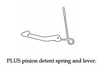
- Print the full-size
version of the pinion detent spring template opposite (PDF file,
A4, 6kb) and use it to set the spring arms to the angle shown. The
springs need to be set fairly accurately to ensure that there will be a
definite minimum pressure on the pinion detents during the keystroke.
- Place the mechanism flat on the bench with the front closest.
- Starting from the right-hand side, fit the pinion detent spring
levers to wire 17. Check that the levers move freely.
- Start wire 16 from the left-hand side and fit a plain 3.35mm spacer,
carry detent pawl (long arm on the left), and a 5mm stepped spacer with
the large end to the right. Continue to the end. Check that the pawls
move freely, and leave them with the long arms facing forward.
- Starting from the left-hand side, fit the transfer gears and the
cam gears to wire 4 through the offset frame arms. Check that all the
gears turn freely.
- Cut a piece of 1/16" rod about 15mm long and round or chamfer the
ends. This will be used as a temporary shaft to fit the numeral wheels
and spring gears into position.
- Arrange the numeral wheels in order to match the colour groupings
in the keyboard. Note that there is one more wheel than key columns.
- Assemble the leftmost numeral wheel, spacer, and pinion onto the
temporary shaft, with the locating finger in the slot between 0 and 9.
- Turn the leftmost cam gear backwards until it stops against the
rear carry pawl. (Pull the pawl forwards if it has moved).
- Place the numeral wheel assembly into position. Align the wheel
so that the zero is in the centre of the raised flat on the frame
plate, then engage the pinion with the cam gear. Feed in wire 5 from
the left-hand side, pushing out the temporary short shaft.
- Check that the wheel spins freely and has minimal side play. If too
tight or too loose, remove and try a different set of parts. The
factory used least 3 different thicknesses of spacers (0.053", 0.060",
0.067"), and sometimes additional shims, to adjust the end play. If you
have no other options, ease the frame plates slightly to adjust the
clearance.
- Turn the numeral wheel forward and check that it stops at 0.
Correct the gear engagement if necessary, then continue with the
remaining columns.
- Starting from the right-hand side, fit the pinion detent levers
and the front carry pawls to wire 5. The detent lever sits astride
the frame plate, with the wire spring in front. Fit a spacer in the
leftmost column to hold the carry pawl in position. Check that all
the pawls and levers move freely. Attach the small coil spring to the
leftmost detent lever (or to all the levers, on the very early models).
- Fit the carry delay (or duplexing) levers and spacers to wire 7.
The long arm of the lever passes in front of the numeral wheel hub and
lies flat against the right-hand side of the frame plate. Attach the
coil springs to the pins on the frame. There is no duplexing lever in
the rightmost column (where there are no incoming carries), nor in the
leftmost (where there is no keyboard mechanism).
- Stand the mechanism on its back with the underside closest. Take a
carry pawl spring and hold it vertically, with the central loop closest
and the upper hook facing away. Pass the lower end down between the
cam gear hub and the rear carry pawl. Engage the top hook with the
hole in the front pawl, then catch the lower end with your spring hook
and engage it with the rear pawl. Keep a finger on the top pawl during
this operation, to stop the spring flying away if it slips off the
spring hook while under tension.
- Carry spring gears
- Sort the carry spring gears into left and right-hand versions.
(The right-hand gears have a longer hub on the flat outer side). Check
that the pins on the inner sides of the gears are not loose, bent, or
damaged.
- Take a pair of gears and fit the carry spring. Wind the right-hand
gear clockwise until its pin passes the left-hand pin twice, then
insert the short temporary shaft. When new, it will take 2 full turns
to pre-load the springs. When they have relaxed after 50 years in
service, it will generally take only about 1.5 turns. If much less
than this, it will be best to add another full turn to avoid the risk
of incomplete carries. (The springs can be wound safely to 4 or 6
turns, eg for the 10/- column on Sterling machines, but do not use
more than necessary).
- Starting from the right-hand side, set the numeral wheel to zero,
and turn the transfer gear forward (counter-clockwise viewed from
the right-hand end) until it stops against one or other of the carry
pawls. It does not matter if this advances the wheel to the left.
- Hold the gear assembly with the tips of your tweezers between the
two pins, so that they are separated by a small distance. Place the
gears into position, engage with the transfer and cam gears, insert
pivot wire 6, and push out the temporary shaft.
- Check that there is still a small but definite gap (0.5-1mm)
between the two pins. If not, remove the spring gears, re-set the
transfer gear, and try again. The spring tension must be held between
the carry pawls, the stop tooth on the transfer gear, and the step on
the cam gear, and not between the two pins on the spring gears. The
register will not operate correctly if the pins are touching.
- The angular position of the pins should be such that the spare
wire 1 can be inserted through hole 3 in the frame and through the
corresponding holes in the two spring gears. This is a service aid
which locks the gears and avoids losing the spring pre-load if it
should be necessary to only partially disassemble the register.
Return wire 1 to its normal position when all the gears have been
installed.
- Checking and adjustment
- Check the clearances around the rear joint of the parallelogram
linkage in each column. Ensure that the pivot pin is not rubbing or
catching on the frame, and not pressing sideways against the tail of
the sector lever. Bend the pivot pin arm and/or sector tail slightly
if necessary.
- Stand the mechanism on its back. Operate the 5 keys and check that
the rear end of the pinion detent spring lever is properly aligned with
the outside end of the sector roller pivot pin. Bend the lever slightly
to adjust.
- Check that the slot at the front of the sector is sitting loosely
on the roller and is not pressed hard sideways. Bend the sector arm
slightly to adjust.
- Press each 5 key and check that there is sufficient clearance
between the sector and the lower carry pawl. The sector can catch on
the carry pawl on the return stroke if it is excessively twisted.
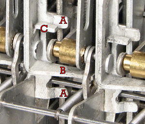
- Watch the sector and pinion during the key downstroke and make
sure that there is no interference. Correct by bending the trip bar
release arm B slightly towards the rear.
- Let the sector engage with the pinion at the bottom of the
keystroke. Lift the pinion detent, allow the key to rise slowly, and
make sure that there is no binding or jerkiness in the
movement of the gears. Adjust the depth of engagement by carefully
bending lug C. It is important that the forward movement is
stopped by lug C, and not by the sector binding on the pinion
or the elbow striking the rear of arm B. There must still be
a small clearance between arm B and the rear of its slot when
the sector is released.
- Check that the alignment of lugs B and C is
generally similar in each column. Investigate and correct any
significant differences.
- Press the 5 key fully down and allow it to rise slowly. Check that
the pin at the rear of the parallelogram linkage lifts the sector tail
far enough to allow the trip arm B to reset fully at the end of
the return stroke. Bend the sector tail slightly to adjust.
- Check and adjust the operation of the keys and the sector trip bar.
If the tabs A are too high, the sector may be released before it
has fully risen, resulting in under-adding. If too low, the keys will
require excessive pressure at the end of the downstroke, and may fail
to trip. It is important that the key movement is stopped by the
sawtooth bar striking the keystem, and not by the trip arm pressing
on the bottom of its slot at the sector elbow. To make these
adjustments, stand the mechanism on its left-hand end with the
underside closest. Press each key in turn, maintain a normal pressure,
and gently rock the sector trip bar with your other hand. There must
be a small but definite movement between the arm B and the
bottom of the slot. Adjust by carefully bending the tabs A.
(To make a bending tool, hacksaw a slot halfway through a piece of
5mm (or similar) rod or bar, about 2mm from the end. Hold the trip bar
with pliers (or another bending tool), place the slot over the side of
the tab, and gently ease it up or down). Check the feel of all the
keys when completed, and make any further fine adjustments.
- Operate the 1 keys slowly and check that the detent arms drop fully
between the teeth of the pinion. There is no adjustment for the detents,
other than ensuring the spring pressure is correct and removing any
burrs or roughness from the tips.
- Lift the pinion detents and check that the numeral wheels return
quickly to zero.
- Set the register to all-9s, add 1, and check that the ripple
carry propagates smartly across the entire register.
- Check the duplexing operation. Clear the register, then press the
5 key in the leftmost column and hold it down. The register remains at
zero. Press 5 twice in the next column to the right. The register
should advance to 10, but the carry will be delayed and the display
will remain at 00. Release the key, and the held column should advance
immediately to 6 (ie, 5 plus the delayed carry). Repeat across all
columns.
- Clear the register. Use three fingers to press the leftmost
5 keys simultaneously, then the 4s, and so on until you have added
all the numbers in all the columns, 3 at a time. If the result is
166...665 you can be fairly confident that the mechanism is working
correctly.
- Clearing mechanism
- Push back wire 11 and fit the clearing latch arm and torsion spring
under the bracket on the right-hand side.
- Take the finger bar which operates the clearing latch release and
check that all the fingers are more or less in line. Stand the
mechanism on its back, insert the bar, and engage it with the forked
end of the latch lever. Start the pivot wire 15 from the right-hand
side. Fit the small stop bracket at (or near) the centre column and
push the wire fully home.
- Check that the two rollers on the pinion detent lifting bail are
free to turn. Fit the bail into position over the detents, with the
rollers at the top rear. Push back wires 4 and 5 to provide clearance
as necessary. Engage the lower arms with the ends of wire 17, with
small spacers on each side.
- Place the large U-shaped actuating lever in position (with the
clamp screw accessible), and insert the 1/4" handle shaft. Adjust
the side arms if necessary so that they are centred on the rollers.
- Fit the coil or torsion spring to the clearing handle. Fit a new
rubber sleeve to the late-model handle.
- With the handle held forward by the latch, position the operating
arms so that they are fully engaged with the rollers, but no further.
Tighten the clamp(s).
- Release the latch and set the register to all 1s. Draw the clearing
handle forward and check that all the numeral wheels return to zero.
Adjust the forward stop if necessary to limit excess travel.
- Check that the handle latches in the forward position, and that
it releases when a 1 key is pressed. Check every column, and adjust
the finger bar as necessary.
- Finishing off.
- Push back the numeral wheel shaft and fit the register mask. The
notches in the end tabs go towards the front.
- Tape a new sheet of rust-inhibiting paper (if available) inside
the base, otherwise use a sheet of plain paper to absorb oil drips.
- Mount the mechanism onto the base. On late models with the die-cast
base, cut new rubber mountings from a strip of 2 or 3mm neoprene
sheet and sit them over the locations on the base, so that the spacers
will press them into position. Be careful not to make the front
mountings too large, or they will foul on the spring gears directly
above. Replace other rubber mountings and bushings as necessary.
- (Early models) Place the felt strip across the back of the
keyboard, then fit the slotted keyplates. Fasten new felt buttons
under the front corners of the two large plates if necessary.
- Cut a new window from 1/16" (or 1.5mm) acrylic sheet. While this
will not affect the operation of the machine, it will make a very big
difference to its appearance.
- Refit the top cover and clearing handle. Check that the cover does
not foul on any of the keys, or cause the keyplates to bind.
- Repeat the test calculations under Checking and Adjustment.
Original text and images Copyright © John Wolff 2008-09.
Use at own risk; beware of errors; suggestions for improvement welcome.
Last Updated: 4 April 2009
Back to: Home
Calculating Machines
The Bell Punch Company
PLUS Technical Description
Tech Index