John Wolff's Web Museum
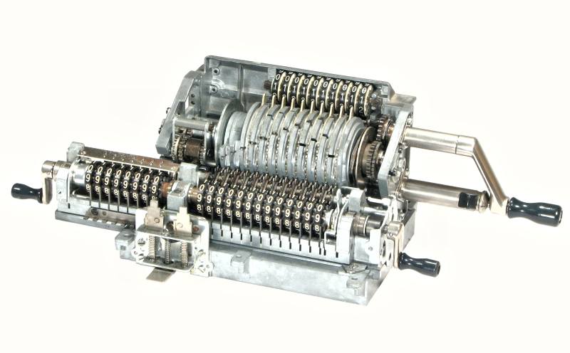
Rebuilding the Original-Odhner Model 239 Pinwheel Calculator
Contents
|
|
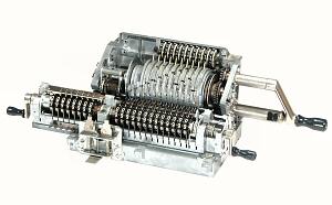
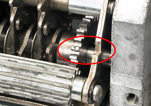
| Odhner 239 mechanism, 1960s |
Introduction
These notes give a detailed step-by-step procedure for a complete
disassembly and reassembly of the Original-Odhner Model 239 mechanical
calculator. They are also applicable, with suitable modifications, to
the other models in the 200 series, and in principle to any Odhner
machine from the 1920s to the 1970s.
The notes have been prepared and refined during the rebuilding of
a significant number of Odhner machines, and may provide a useful
guide to anyone faced with a similar task. The sequence of operations
described works well for me, but comes with no guarantees. No
responsibility will be taken for any consequences arising from the use
of these notes by others.
These notes are intended to be read in conjunction with two other
documents in this section:
Please study this material carefully before commencing your overhaul
and refer frequently as you proceed, especially to the illustrations
in the Technical Description.
If you use these notes to rebuild an Odhner I would appreciate
receiving your feedback, comments, or suggestions for improvement
via the enquiry form.
Disassembly
Please review the material in the
Notes on overhauling a mechanical
calculator before proceeding. It is suggested that you print a copy
of these notes, and tick off each step as it is completed. An Odhner
239 can be completely disassembled in an hour or two, provided that no
major problems are encountered.
- Carriage and covers
- Remove the carriage stop pin and its mounting plate (2 screws
through the large hole in the bottom cover).
- Hold down the carriage release tab and slide the carriage out to the
right-hand side. If the carriage fouls on the rotor or other mechanism,
leave it and continue.
- Remove the four screws and washers in the rubber feet and lift off
the bottom cover.
- Remove the four screws holding the side covers to the base. Slide
the covers downwards at the front, then forward, to disengage the
internal clips. The movement required is only about 1 or 2mm.
- Remove the winding handle stop plug and sleeve (2 special screws
from underneath) and remove the right-hand cover plate.
- Remove the top panel (2 screws each side), and the rear panel
(3 screws from underneath).
- Pull off the carriage shift buttons and remove the front panel
(3 screws from underneath).
- Main body
- Remove the rear panel and check dial mechanism (4 screws) and
disassemble (9 screws). Be very careful of the light springs under the
detent levers.
- Remove the rotor bearings from the side plates (3 screws each side).
- Lift the rotor from the left-hand end, disengage the right-hand
end, lift out and set aside.
- Remove 2 screws from underneath into each side plate. Ease the
plates up off their dowels, remove and set aside.
- Remove the interlock plate and bell assembly (3 screws).
- Remove the rotor interlock lever and pivot rod (2 screws underneath).
- Remove the 4 screws holding the carriage shift mechanism. Ease
the mechanism away from its dowel pins and disassemble.
- Left-hand side plate.
- Refer to the illustrations in the
Technical Description
and disassemble the counter reversing mechanism. When removing the
reversing body and gears (on the front shaft), be careful of the
tiny detent ball and spring inside the right-hand gear.
- If it is necessary to disassemble the reversing body, note that
the plain pin is staked at each end. Be careful of the tiny ball
and spring under the T-bar, and the larger spring under the
half-round pin.
- Right-hand side plate.
- Remove the spring, wire retainer, and circlip at the bottom front
and withdraw the sliding plate and shaft.
- If necessary (and if you have the facilities), drive out the tapered
pin and remove the main gear and drive shaft. Disassemble the non-return
pawl, spring, and wire ring.
- Disassemble the handle and locking pin.
- Carriage
- Pull off the back-transfer button and remove the carriage covers
(4 screws). Turn the clearing handles upwards to remove the end covers.
- Roll the carriage onto its back. Carefully loosen the two screws
holding the metal strip under the accumulator until the spring pressure
is released, then remove the strip and lift out the 12 carry lever detent
springs. Temporarily replace the strip to retain the detent pins. Roll
the carriage forward onto its base.
- Carefully loosen the three screws holding the right-hand end plate
until the spring pressure is released, then remove the screws.
- Working from the rear, observe that the sheet-metal frame of the
tens-carry mechanism behind the counter register is held in place by a
pin near the top of each side. The inner pin is formed on the end of
the accumulator star wheel shaft. Remove the screw and washer holding the
shaft to the centre pillar, then push the shaft outwards (to your left)
until it is clear of the carry mechanism. Remove the short pin
on the opposite side by pushing it fully out to the right. Lift the
interlock arn around the centre pillar, then lift out the carry
mechanism and set aside.
- Remove the back-transfer stop plate from the accumulator end pillar
(on your left).
- Continue pushing the accumulator star wheel shaft out to your left,
removing the bracket and spacers around the centre pillar, the star
wheels, and the back-transfer assembly.
- Remove the 4 screws and narrow retainer plates at the rear of the
accumulator register. Remove the two shafts, carry levers, support
arms, and spacers.
- Roll the carriage onto its back, remove the retainer strip again,
and push the carry lever detent pins out of their holes with a suitable
wire or tool. Be sure to recover all 12 pins. Note that there is no
detent on the bell lever in the 13th place.
- From the front, disconnect the spring from the back-transfer latch.
Fold the register retainers (each end) forward and clear of the
registers. Remove the bearing retainer plate and screw from the pillar
between the registers, then ease both register assemblies up and out
together.
- Disassemble the two registers, but keep them separate. Take careful
note of the sequence and orientation of the components as they are
removed from the shafts. The tapered pins in the clearing handles can
be driven out towards the front (if necessary), but take care to avoid
damage.
- Remove the screw and washer securing the detent lever shaft (at the
right of the centre pillar). Carefully push out the detent shaft and
remove the detent levers, balls, and springs. The balls are sometimes
held by a ring of dirt or oil at the top of the hole, and can spring
away unexpectedly when disturbed.
- Drive out the small rolled pin holding the arm at the outer end
of the back-transfer gear assembly and remove the gears and spacer.
- Counter carry mechanism
- From the rear, remove the circlip and long gear.
- Remove the circlip inside the inner end of the star wheel shaft,
then remove the shaft and star wheels.
- Lift and remove the carry levers.
- Ensure that the sliding collars are not stuck to their shaft.
Push out the shaft, leaving the collars and drive gear behind on the
toothed key strip. Remove and separate the components.
- Remove the spring plates and 7 detent balls (2 short screws from
underneath).
- Main rotor
- Withdraw the toothed locking bar and ring from the right-hand end.
- Remove the set screw in the round nut at the left-hand end of the
rotor discs. Wrap the rotor in a heavy cloth and hold it firmly, then
loosen the nut with a suitable C-spanner or a length of 4mm drill rod.
The nut will usually be very tight. Alternatively, grip the round nut
in a vice, tighten only as much as necessary, wrap a rag around the
rotor, grip firmly with both hands, and loosen the nut.
- Prepare a base for working on the pinwheel rotor by drilling a
10mm hole in a block of wood about 75 or 100mm square. Stand the rotor
shaft upright in the base.
- Note that the round nut is carried on a threaded collar which can
slide along the mainshaft. Unscrew the nut until it is level with the
end of the thread, then push it inwards. Push the inner gear and the
adjacent wide C ring inwards into the space created. Remove the split
C ring from between the two wide rings.
- Push the outer gear inwards and remove the split C ring from the
recess in its outer face.
- Remove the gears, then remove and disassemble the pinwheels one
at a time. Use plenty of solvent (and patience) if the wheels are
stuck to the shaft, and clean the residues from the shaft as each
disc is removed. Proceed very carefully to avoid damage to the
die-cast alloy. Withdraw the round alignment rod as soon as it comes
free. Be careful of the internal springs on the detent pawls.
- The driving gear assembly at the right-hand end is keyed to the
shaft and secured by another recessed C-ring. It is often stuck tight
with decayed oil. If removal proves difficult, leave it in place
rather than risking damage to the mainshaft.
Cleaning
Please review the general information about cleaning and checking
in the Notes on overhauling a
mechanical calculator, and proceed as described. Initial washing
and cleaning will take about 3 hours.
Reassembly
Please review the material on Reassembly in the
Notes on overhauling a mechanical
calculator.
Moving parts should be lubricated sparingly as they are assembled.
Apply a thin film of oil to steel parts with a (slightly) oily rag to
prevent rust, and apply a minimum of light oil to gears, pivots and
bearings. The pinwheels and setting rings should not be oiled.
In the notes following, screws listed as (eg) M3x8 are 3mm diameter,
standard pitch (0.5mm), and 8mm overall length. Tension springs listed
as (eg) 3x10x0.3 are 3mm diameter, 10mm closed coil length, and 0.3mm
wire diameter.
Final cleaning, checking, and re-assembly can be completed in about
4-6 hours if no major problems are encountered.
- Carriage shift mechanism
- Attach the 2 springs 3x4x0.26 from the shift pawls on the rear of
the large plate to the hole between.
- Place the long compression springs over the key stems. To make
assembly easier, compress the springs and temporarily tie them shut
with a piece of fine wire or string.
- Insert the key stems into their support bracket with the pins
facing rearwards.
- Place the support bracket onto the flat side of the larger plate.
Engage the pins with the slots in the two shift pawls behind, engage
the locating pins between the plates, and fasten with 2 screws M3x6.
- Attach the 4x8x0.3 spring to the flat end of the carriage release
arm so that it sits above the larger hole. Place the rubber washer
over the spring. If the washer is missing or damaged, cut a replacement
from 1.5mm neoprene sheet.
- Fit the carriage release arm to the rear of the assembly. Attach
the top of the spring so that it lies evenly between and parallel
to the keystems.
- Release the compression springs and check that the keys and the
carriage release arm move freely.
- Base plate
- Mount the interlock plate and bell assembly to the base with
3 screws M3x8.
- Locate the carriage shift mechanism on its dowel pins and attach
with 4 screws M3x8.
- Invert the baseplate and install the interlock lever between the
shift mechanism and the interlock plate on the bell assembly. Fasten
the short axle with 2 screws M3x12.
- Right-hand side plate
- Asemble the winding handle and locking pin.
- Assemble the drive gear and non-return pawl. Note that the pawl is
not symmetrical. Place it on the drive gear with the long pointed tooth
downwards and the side with the more equal spacing on the right. Then
fit the spring washer (bent side down) and the wire retaining ring.
- Fit the winding handle in its bearing. Fit the drive gear with
the long tooth of the non-return pawl facing the centre of the rotor
bearing housing and insert the tapered pin from the top. Check that
the long tooth swings (approximately) equal distances to either side
of the rotor bearing, then support the hub of the gear and drive in
the tapered pin.
- Check that the large pin at the top rear of the sliding interlock
plate is still firmly rivetted in place and correct as necessary. Fit
the shaft into the handle stop pillar and fit the circlip to the
locating pin at the bottom front. Fit the 4x7x0.4 spring from the
plate to the wire retainer (through the hole in the frame).
- Temporarily fit the rotor clearing sleeve, shaft extension piece,
and end plug to the handle stop pillar and secure with the two special
screws. Ensure that the assembly slides freely.
- Left-hand side plate
- Check the gears in the reversing mechanism for damage. The small
pressed-metal gears rivetted to the end plates may be badly worn, or
may have bent or broken teeth if the machine has been forced. Repair
as necessary.
- Place the die-cast side plate flat on the bench with the inner
face upwards.
- Stand the two 5x28 pillars in the rear holes in the side plate,
flanged ends down.
- Place the bright plate with two gears over the pillars with the
long arm facing upwards and forwards. Fasten with 2 screws M3x12,
1 M3x7, and 3 flat washers from outside.
- Assemble the reversing body. Check that the pointed T-bar
locates positively in its three detents, and that the spring-loaded
pin moves freely. Secure the plain pin in the original manner.
- Fit the tiny compression spring 2.2x5x0.5 and 3/32" ball into the
hole in the right-hand end of the reversing body shaft, then fit the
small gear with the cam side inwards and the notch over the ball.
Put on your safety glasses, insert a suitable tool (eg the back of a
knife blade) between the cam and the gear, press the ball down
into the hole, then push the gear fully home. The ball must rest in the
detent V-notch in the gear, and not in the gap between the gear and the
cam. When correctly fitted, the ball will be centred inside the gear
and clearly visible from the outside.
- Fit the larger cam and gear to the left-hand end of the reversing
body, then the large gear with the counter operating finger. The cam
and the operating finger both face towards the central body.
- Stand the large end of the assembly in the bearing in the
left-hand plate. Fit the slotted resetting arm into the small pivot
hole. Fit two long spacers over the pillars, then fit the top plate.
Insert the third pin and spacer at the front and fasten with 3 screws
M3x7 and flat washers.
- Attach the spring 2.8x4x0.3 to the rear of the resetting plate.
- Fit the side plate assembly to the base with 2 screws M4x14. Firm
up but do not fully tighten.
- Pinwheel rotor assembly
- Note that there is one pinwheel each numbered 1 (or 1a) and 6,
but two sets numbered 2 to 5. Each wheel in these sets has two numbers
(2-10, 3-9, etc) and two possible locations for the pairs of carry
pins. Use the numbers next to the installed carry pin. There are two
sets of setting rings numbered 1 to 5, which match the first number
on the pinwheel. The second No.1 ring goes on pinwheel 6.
- Fit the driving gear and flange assembly to the plain end of the
shaft, then fit the thick C ring into the single groove.
- Stand the shaft upright in your block of wood.
- Prepare pinwheel 1, setting ring 1, and pinwheel 2.
- Place pinwheel 1 onto the shaft. Fit the 9 pins, leaving them
slightly outside the edge of the wheel. Place the detent pawl and
spring into position, but do not compress the spring. Place the
setting ring over the wheel, engage the pins with the slot, engage
the hub, then press the detent pawl into position against its spring.
Hold the setting ring and immediately fit pinwheel 2 to keep the
assembly together.
- Hold down pinwheel 2 and check that the setting ring rotates
easily. The ring may catch on the first couple of moves as dust gets
pushed aside. If problems persist, look for nicks or damage to the
discs or rings, or try reversing the offending pin.
- When the operation is correct, continue in the same manner
to disc 11 and carry sectors 12 and 13.
- Check that the two rows of carry pins progress uniformly across
the rotor, then fit the alignment rod into the holes.
- Fit the end disc with the concave side out.
- Repair the threads on the inner collar where they have been
damaged by the set screw. Fit the round nut so that the shouldered end
of the collar and the set screw hole in the nut are both towards the
outside.
- Place the collar assembly, small gear, two wide C rings, and large
gear onto the shaft.
- Fit the first split C ring into the outermost groove on the shaft.
Slide the large gear outwards so that the split ring is held in the
recess in its outer face. Fit the second split ring between the two
wide rings. Firm up the round nut.
- Drop the rotor and wood block firmly onto the bench to settle
the discs, then tighten the round nut. Repeat several times until
fully tightened.
- Operate all the setting rings through their full stroke. The rings
should move evenly over the detents in both directions, with no sign
of stiffness or sticking. Correct as necessary. When all is well,
re-tighten the round nut and tighten the set screw.
- Fit the toothed locking bar and ring from the driving end. Check
that it has no effect when fully inserted, but locks the setting rings
when withdrawn 2-3mm.
- Pinwheel rotor installation
- Check that the two rotor bearings can be inserted easily into
their mountings. Ease any scrapes or nicks around the bearing, or
around the housings in the side plates. The shorter bearing goes
on the right-hand side. Remove the bearings.
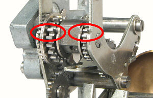 Check that the right-hand gear in the counter reversing assembly is
still in its detent position. Rotate the gears so that the timing
marks on their cams (adjacent to the central body) align with the
V-notches in the fronts of the sub-frame plates (see illustration
opposite).
Check that the right-hand gear in the counter reversing assembly is
still in its detent position. Rotate the gears so that the timing
marks on their cams (adjacent to the central body) align with the
V-notches in the fronts of the sub-frame plates (see illustration
opposite).
- Set the handle in its stop and the rotor setting rings to zero
(fully rearward).
- Hold the rotor with the setting levers one place rearward of
top. Assemble the right-hand side plate to the rotor so that the rotor
locking ring engages with the large pin at the top rear of the sliding
interlock plate.
- Hold the rotor and side plate together and insert the free end
of the rotor shaft into the left-hand bearing housing (no bearings
yet). Lower the right-hand side plate onto its dowels and fasten with
2 screws M4x14. Firm up but do not tighten fully.
- Lift the rotor clear of the driving gear and turn it until the
interlock plate on the bell assembly can be lifted into the notch
in the rotor end disc. Engage the driving gears and insert the right-hand
bearing.
- Engage the gears on the left-hand side. Check the timing marks,
correct as necessary, then insert the bearing.
- Fit the bearing covers and fasten temporarily with 1 screw M3x8
each side.
Adjust the end stops to roughly align the gears. Final adjustment
will be made after the carriage is installed.
- Check the reversing operation. Carefully make a forward turn and
watch as the counter drive pawl passes through the cut-out in the
rotor shaft. The pawl will foul on the shaft if the assembly is
incorrect, and may cause damage if turned vigorously. At the end of
the turn, check that the T-bar has moved to the left, and the timing
marks have returned to their aligned positions. Lift the rotor
interlock plate and check that it resets the T-bar to the centre
position. Repeat for a backward turn (in which the T-bar moves to
the right). Remove the rotor bearing and re-set the gear engagement
if necessary.
- When all is correct, fit the remaining 4 screws M3x8 to the
bearing cover plates.
- Rear panel and check dial
- Check that all the detent pawls are free to move. Carefully fit
the springs into their holes and fold the detents over.
- Fit the narrow star wheels onto their shaft and attach with 2
screws M3x10.
- Fit the numeral wheels onto their shaft with the flat washer at the
left. Replace any shims on the right. Fasten with 2 screws M3x12.
- Assemble the wide star wheels and the long shaft onto the slotted
locating plate and fasten with 2 screws M3x8. Check that the wheels
turn freely.
- Place the wide star wheel assembly in position, fasten the retainer
strips with 2 screws M3x8, and fit the shouldered screw at the bottom
left. Check that the plate slides freely between the two stops.
- Slide the plate to the left and turn the check dials downwards
until they stop at zero.
- Place the handle in its stop and the setting rings at zero.
- Working from the rear, place the panel in position on its dowels.
Look through the rectangular cutout and engage the notch in the
sliding plate with the tab on the handle interlock plate. Fasten with
4 screws M3x8.
- From underneath, tighten the four M4 screws into the side plates.
- Check that the dial operates correctly. If the setting rings are
locked, push the locking bar slightly inwards to release them. (The
locking mechanism will be adjusted until after the rotor has been
aligned with the carriage).
- Carriage preliminaries
- The die-casting alloy can move slightly with time, so it is
advisable to check the carriage alignments first to avoid difficulties
during assembly. Proceed as follows:
- Insert the empty carriage into the base and check that it moves
smoothly from end to end. Stiff spots will leave tell-tale marks on
the bearing surfaces, which can be eased with a fine file or scraper.
- Fit the carriage positioning rack (teeth down) at the front of
the counter register and fasten with 2 screws M3x8. Check that the
shift controls operate correctly.
- Check the fit of the three register shaft bearings in their
housings. Remove any nicks, scrapes, or spurious die-cast metal to
ensure a smooth fit.
- Check that the detent shaft is straight, and that it can be
inserted smoothly into place at the front of the carriage. Correct
as necessary.
- From the rear, fit the lower 4x70mm shaft, the two star wheel
support arms, and the two spacer washers at the right of the arms.
Note that the spacer washers are filed flat on the bottom.
- Feed in the upper 4x93mm shaft from the outer end. If the shaft
is tight, ease the holes or file the supporting surface until the
fit is smooth but not loose.
- Temorarily fit the 4 shaft retainers and screws M3x8.
- Check that the star wheel shaft is straight. Check that it passes
smoothly through the outer pillar and the intermediate supports, and
seats properly in the centre pillar. Adjust as necessary.
- When all alignments are correct, loosen the 4 retainers and remove
the upper shaft.
- Carriage registers
- If the counter clearing handle has been removed, place the bearing
over the shaft, fit the spring into the hollow end, then the narrow
flat washer. Place the handle in position, align the holes, compress
the spring, and insert the tapered pin from the front. Looking from
the outer end with the handle in its normal position, the clearing
teeth should face towards 7 o'clock.
- Fit the pressed-metal cup over the cam and pin, then fit the
shim washer and numeral wheels.
- Fit the interlock cam with the cam facing the end of the shaft.
- If the accumulator clearing handle has been removed, place the
large flat washer over the shaft, followed by the spring, sleeve,
thin flat washer, and the carriage end plate. Place the handle in
position, align the holes and insert the tapered pin from the front.
Looking from the outer end with the handle in its normal position,
the clearing teeth should face towards 1 o'clock.
- Fit the back-transfer operating lever, forked lifting lever and
wire retainer to the accumulator bearing and place onto the shaft.
- Fit the back-transfer release cam with its smaller hub inside the
shaft bearing.
- Fit the numeral wheels, then the interlock cam with the cam
facing the end of the shaft.
- Place the compression springs and detent balls into their holes
in the carriage frame. Note that the counter detents have shorter
springs.
- Feed in the detent lever shaft from the right-hand side. Fit the
register retainer arm (big end down), back-transfer latch, accumulator
detents (short arm vertical at the front), counter detents, and the
left-hand retainer arm. Secure the shaft with 1 screw M3x7 and flat
washer at the right of the centre pillar.
- Open the two bearing retainers, and pull the back-transfer latch
forward.
- Check that both register clearing pins are in their normal
positions (at the bottoms of their cams).
- Fit both register shafts into the centre bearing (groove to right).
Align the end bearings with their curved faces uppermost and place the
assembly above the three pillars.
- Attach the 4x7x0.6 spring between the back-transfer lifting arm
and the latch lever at the front. Ease the register assembly down into
the carriage frame, keeping the back-transfer arms pointing upwards
and the latch forward.
- Close the outer bearing retainers, fit the centre retainer
(1 screw M3x8), and attach the right-hand end plate (3 screws M3x8).
- Turn all the dials by hand and check the detent and clearing
operations.
- Check that the back-transfer control raises, latches, and releases
the lifting arm.
- Engage the back-transfer, rotate the accumulator clearing handle,
and check that the lifting arm drops just before the end of the turn.
- Accumulator carry mechanism
- Working from the rear, feed in the upper 4x93mm shaft from the handle
end and fit the carry levers. The bell lever (with the extra tail) goes
last, next to the centre pillar. Tighten the 4 retainer plates, then check
that the carry levers all move freely.
- Assemble the wide back-transfer gears onto their shaft, hubs first,
then the 3.5mm spacer. Fit the outer arm, align the holes, and press
in the rolled pin. Place the assembly in position behind the register,
with the end of the shaft engaged with the fork in the lifting arm.
- Feed in the star wheel shaft through the end pillar, then through
the register retainer arm and back-transfer arm. Some machines have
spacers on one or both sides of the back-transfer arm, while others have
them as part of the arm.
- Install the star wheels and feed in the shaft to retain. Continue
through the inner back-transfer arm, 3.5mm spacer, and the interlock
arm around centre pillar.
- Fit the 0.5mm shim washer (if present) between the centre pillar
and the counter side of the interlock arm.
- Fit the M3x7 screw and flat washer into the rear of centre pillar
to hold the accumulator star wheel shaft, but do not tighten.
- Check that the register dials and carry levers all move freely.
It may be necessary to remove the star wheels and ease the intermediate
supports sideways to equalise the clearances along the shaft. The bell
lever in particular must be completely free.
- Fit the back-transfer stop to the rear of the handle-end pillar
with 2 screws M3x7. Check that the back-transfer gears rise, latch,
and reset correctly.
- Roll the carriage onto its back and drop in the carry lever
detent pins. The wedge at the bottom of the pins must be aligned
horizontally, ie, along the carriage axis. Insert the springs and fit
the retainer strip with 2 screws M3x7.
- Check that the carry lever detents all operate smoothly. Note that
there is no detent on the bell lever.
- Place a straightedge across the carriage base and check that the
edges of the 2 screw heads do not extend beyond the level of the base.
File the screw heads if necessary to ensure that they do not scrape on
the bearing surfaces in the machine base. (You may find 2 of the screws
with heads already chamfered).
- Counter carry mechanism
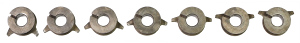 Find the sliding collar with the operating fingers closest
together. Place it on the bench with the keyway at 10 o'clock and the
fingers pointing downwards. Line up the remaining six collars to the
right with the keyways in the same position and the fingers at gradually
increasing angles. The fingers on the rightmost collar will be facing
slightly upwards.
Find the sliding collar with the operating fingers closest
together. Place it on the bench with the keyway at 10 o'clock and the
fingers pointing downwards. Line up the remaining six collars to the
right with the keyways in the same position and the fingers at gradually
increasing angles. The fingers on the rightmost collar will be facing
slightly upwards.
- Hold the key strip with the teeth upwards and the wide tooth (with
the hole) on your right. Place the drive gear immediately to the left of
the wide tooth, with its hub to the left and its keyway engaged with the
next tooth.
- Add the collars in order (right to left) with the fingers on the
right and the keyways engaged with the teeth on the key strip.
- Working from the rear of the carry frame (long arms facing away), put
the collar assembly in position (small end first) with the gear resting
in the slot in the base.
- Insert the plain end of the shaft from your left-hand side, and
assist the collars onto the shaft. The last two teeth on the key strip
are positioned on each side of the right-hand frame. Be careful handling
the assembly prior to installation as the shaft can easily fall out.
- Push the collars to the left and check that both rows of fingers are
aligned at uniformly increasing angles.
- From the front, hold each carry lever with the long end up and the
open side away. Pass the long end up through the slot in the top plate,
fit the open side into the V-groove in the collar, then drop the bottom
end into the slot in the base.
- From the rear, start the plain end of the star wheel shaft from your
left-hand side. Fit the 1.8mm spacer, the star wheels with their hubs
to right, and the 8.5mm spacer at the right. Fit the circlip at the
inside of the left-hand side.
- Fit the long gear and circlip.
- Invert the frame and fit the seven 3/32" detent balls, two spring
plates, flat strip, and 2 short screws M3x4.
- Check that the carry levers move and latch correctly. Rotate the long
gear as necessary to allow the operating fingers to engage with the star
wheels. (The engagement will be synchronised through the gearing when the
carriage is installed).
- From the rear of the carriage, push back the accumulator star wheel
shaft until it is clear of the counter side. Check that the curved
counter register retainer arm is in position against the end pillar.
Lift the central interlock arm and insert the carry mechanism.
Hook the long forward arms over the detent shaft at the front.
- Push the accumulator star wheel shaft inwards to engage with the
hole at the top of the carry assembly, then insert the shouldered pin
from the other side. Tighten the retaining screw on the star wheel shaft.
- Installing the carriage
 Examine the narrow gear at the outer end of the counter carry
mechanism and locate the tooth marked with a dot on its tip. Align
this dot with the V mark on the adjacent frame (as illustrated).
Examine the narrow gear at the outer end of the counter carry
mechanism and locate the tooth marked with a dot on its tip. Align
this dot with the V mark on the adjacent frame (as illustrated).
- Support the front edge of the machine on a small block so that the
rotor interlock lever (under the left-hand side) is clear of the bench.
- Set the winding handle in its stop and the two clearing handles in
their home positions.
- Lift the back-transfer interlock arm (under the front right-hand
side of the rotor) to its upper position.
- Slide the carriage in from the right-hand side until it stops
against the shift mechanism. Press the carriage release lever and
continue carefully. Look in horizontally from the left-hand side and
assist the long gear in the carriage to engage with the driving gear
in the main body. Release the carriage release lever and push the
carriage further until it locks. Check the alignment marks again and
repeat the installation until correct.
- Temporarily fit the carriage stop pin (under).
- Final adjustments
- Support the front edge of the machine on a small block so that the
rotor interlock lever (under the left-hand side) is clear of the bench.
- Check the operation of the carriage shift mechanism, and ensure
that the carriage is held securely in each position. Set the carriage
fully to the left.
- Set the first and last rotor discs to 9 and turn the handle carefully.
Check that the extended pins on the rotor are properly aligned with
the accumulator star wheels, and that the counter drive pawl is centred
over the corresponding counter star wheel. Adjust the bearing end stops
to provide the best alignment with minimal end play, then tighten the
lock nuts.
- Temporarily place the top cover in position and check that the
setting rings do not rub on the sides of their slots. Repair any bent
or damaged slots, and re-adjust the rotor position if necessary. Remove
the top cover when satisfactory.
- Set the rotor to zero and the carriage fully to the left. Give the
winding handle one forward turn and observe that the T-bar in the
counter reversing body has moved to the left. Slowly rotate the counter
clearing handle and watch the movement of the slotted resetting arm under
the reversing body. Note whether the arm rises far enough to reset the
pointed T-bar to its central position.
- Operate the accumulator clearing handle and note whether the
interlock plate rises far enough to prevent the rotor turning during
clearing, but not so far as to bring the resetting arm into contact
with the T-bar.
- These movements are frequently inadequate, due to wear on the cam
follower (ie, the interlock arm around the central pillar on the
carriage). Correct by extending the appropriate vertical finger on the
interlock plate, or building up the operating surface of the interlock
arm. A suitable piece of steel or brass can be soldered, brazed, or
screwed into position, then filed down to suit. If repairs have been
made, repeat the previous two tests to ensure satisfactory operation.
- Set the rotor to zero and the carriage fully to the left. Give the
winding handle one forward turn to set the counter direction, then one
backward turn to return the count to zero. Very carefully make a second
backward turn, and observer the progress of the secondary carries
("ripple carry") as the register changes to all 9s. Make a forward turn
and watch as the register returns to zero. The operation should proceed
smoothly and easily in both directions. Problems are most likely due to
incorrect timing when installing the carriage, or excessive wear in
the gears in the reversing mechanism.
- Check that the setting rings are locked when the handle is pulled
outwards, and that they become free when the handle is in its stop.
Correct as necessary to obtain prompt and reliable operation.
- Check the operation of the rotor quick-clearing mechanism. Hold the
button on the handle stop pillar inwards with your thumb, pull out the
handle, and turn forwards until it stops (about 1/4 turn). Return the
handle to its stop. It may be necessary to adjust the lateral position
of the sliding gear assembly on the rear panel by bending the
interlocking tabs.
- Clear the setting rings using the quick-clearing mechanism. Set the
carriage to its leftmost position and check that the back-transfer gears
rise and latch correctly. Adjust the back-transfer stop and the latch
lever if necessary to obtain full engagement without binding.
- Check the operation of the back-transfer interlock. Give the handle
a forward turn, then check that the back-transfer lever can not be
engaged. Reset the interlock by using the quick-clearing mechanism,
then check that the back-transfer gearset rises, latches, and releases
correctly. The interlock is operated by an arm attached to the handle
interlock plate (under the right-hand end of the rotor), which may be
bent as a result of forcing or incorrect removal of the carriage.
Correct as necessary.
- Check that the left-hand arm of the back-transfer gear assembly
does not foul on the rotor end plate. Adjust if necessary.
- Set the carriage to the left. Set a 1 in the first rotor position,
crank forwards and backwards, and check that ripple carries operate
smoothly in both directions on both registers.
- Verify all operations with suitable test calculations.
- Finishing off
- Assemble the perspex windows and decimal indicators in the covers.
- Remove the carriage and install its covers with 4 trim screws M3x8.
- Fit the back, front, and top covers (in that order) to the main
body. Replace the carriage shift buttons and back-transfer button.
- Remove the handle stop plug and clearing sleeve. Fit the side
covers, sliding them rearwards then upwards to engage the internal
clips. Tighten the clips first if necessary. Fasten with 4 screws
M3x7. Replace the clearing sleeve and handle stop plug.
- Reinstall the carriage, paying attention to the counter carry
timing. From underneath, re-fit the carriage stop pin, and check
that the carriage locks securely at each end of its travel. Rotate
the stop pin or adjust the eccentric if necessary.
- Fit the bottom cover and rubber feet. Satisfactory replacement feet
can be cut from 4.5mm neoprene sheet with a 30 or 35mm (1.5") wad punch.
Original text and images Copyright © John Wolff 2009-20.
Use at own risk; beware of errors; suggestions for improvement welcome.
Last Updated: 15 September 2020 - many minor changes and clarifications.
Back to: Home
Calculating Machines
Pinwheel calculators
Original-Odhner
Odhner mechanism
Tech Index