John Wolff's Web Museum
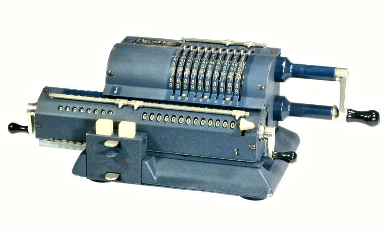
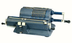
Rebuilding the Original-Odhner Model 127 Pinwheel Calculator
Contents
|
|
| Original-Odhner Model 127, c.1950 |
Introduction
These notes give a detailed step-by-step procedure for a complete
disassembly and reassembly of the Original-Odhner Model 127 mechanical
calculator. The Odhner 127 is a relatively simple and straightforward
machine, and is an ideal place to learn the principles on which all
pinwheel calculators are based.
The notes have been prepared and refined during the rebuilding of
a significant number of Odhner machines, and may provide a useful
guide to anyone faced with a similar task. The sequence of operations
described works well for me, but comes with no guarantees as to its
efficiency or appropriateness. No responsibility will be taken for any
consequences arising from the use of these notes by others.
These notes are intended to be read in conjunction with two other
documents in this section:
Please study this material carefully before commencing your overhaul
and refer frequently as you proceed, especially to the illustrations
in the Technical Description.
I would appreciate receiving your feedback, comments, or suggestions
for improvement via the
enquiry form.
Disassembly
Please review the material in the
Notes on overhauling a mechanical
calculator before proceeding. It is suggested that you print a copy
of of this procedure, and tick off each step as it is completed.
The normal disassembly procedure following can be completed in
an hour or two, provided that no major problems are encountered.
If problems do arise (eg the shift mechanism is inoperable, the
carriage is stuck, or it fouls on the rotor or other mechanism), an
alternative procedure is provided at the end. The normal procedure
should be used whenever possible.
- Preliminaries
- Remove the top and side covers.
- Remove the four special screws and washers in the rubber feet and
lift off the bottom cover.
- Remove the carriage stop pin (2 screws from underneath).
- Hold down the carriage release tab (at the bottom of the shift
mechanism) and slide the carriage out to the right-hand side.
- Remove the back cover, bracing plate, and quick-clearing comb.
- Pull off the carriage shift buttons and remove the cover from the
shift mechanism.
- Main body
- Remove the rotor bearing and cap from the left-hand side plate.
- Remove the rotor bearing from the right-hand side plate. Recover
any shims stuck to the face of the bearing or remaining behind on
the shaft.
- Lift the rotor to disengage the locking ring at the right-hand
side, then lift the left-hand end up through the channel in the side
plate and remove.
- Remove 2 screws from underneath into the left-hand side plate.
Ease the side plate up off its dowels and remove. Remove the circlip
and the counter drive gear.
- Remove 2 screws from underneath into the right-hand side plate.
Remove the side plate from its dowels and set aside.
- Remove the bell and interlock assembly (3 screws). There is
generally no need to disassemble this unit further unless repairs
are necessary.
- From underneath, remove the short axle, two levers, and the
quick-clearing pin and spring in the bushing at the rear.
- Remove the carriage shift mechanism and disassemble.
- Remove the carriage retainer strip at the top front of the
baseplate.
- Right-hand side plate
- Unhook the return spring and remove the sliding interlock plate
and shaft from the side plate.
- Support the front face of the winding handle and drive out the
tapered pin from the rear. Withdraw the drive gear and shaft and
disassemble the non-return pawl.
- Press the handle locking pin outwards until the small rolled pin
is visible in the collar at the outer end of the handle. Drive out
the pin and disassemble the handle.
- Remove the outer cap and the inner eccentric bush from the handle
stop post.
- Remove the handle shaft bearing and the stop post.
- Pinwheel rotor
- Loosen the set screw in the round nut at the left-hand end. Wrap
the rotor in a heavy cloth and hold it firmly, then loosen the nut with
a suitable C-spanner (or a length of 4mm drill rod). Alternatively,
grip the round nut in a vice, tighten only as much as necessary, wrap
a rag around the rotor, grip firmly with both hands, and unscrew. The
nut will usually be very tight.
- Prepare a base for working on the pinwheel rotor by drilling a
10mm hole in a block of wood about 100mm square. Stand the rotor
shaft upright in the base.
- Note that the round nut is carried on a threaded collar which can
slide along the mainshaft. Unscrew the nut until it is level with the
end of the collar, then push it inwards. Push the gear and sleeve
inwards into the space created and remove the C ring from the outside
of the gear. Remove the gear, split sleeve, nut assembly, and the
pressed-metal end disc.
- Remove the circlip from the 3.5mm alignment rod if it is visible
at the top of disc 13. (On some versions of the 127 the rod only
extends to disc 10).
- Remove carry wheels 13, 12, and 11. Use plenty of solvent (and
patience) if the wheels are stuck to the shaft, and proceed very
carefully to avoid damage to the die-cast alloy.
- Remove the circlip from the end of the alignment rod if it appears
at pinwheel 10, then remove and disassemble the pinwheels one at a
time. Be careful of the internal springs on the detent pawls.
- The driving gear is a press fit on the right-hand end of the shaft.
It can be cleaned well enough in place and does not need to be removed
unless repairs are needed.
- Carriage
- Pull off the back-transfer button and remove the carriage covers.
If the front cover has an extra screw below the 9th place in the
accumulator, be sure to recover the spacer behind.
- Roll the carriage onto its back. Carefully loosen the 3 screws
holding the metal strip under the accumulator until the spring pressure
is released, then remove the strip and lift out the carry lever detent
springs. Temporarily replace the strip (1 screw) to retain the detent
pins. Roll the carriage forward onto its base.
- Remove the back-transfer stop plate from the rear of the right-hand
end pillar.
- Remove the screw and washer holding the star wheel shaft to the
centre pillar. Push out the shaft and remove the star wheels,
the back-transfer assembly and spacers, and the interlock arm and
spacers around the centre pillar.
- Remove the 4 screws and narrow retainer plates at the rear of the
accumulator register. Remove the two shafts, carry levers, support
arms, and spacers.
- Roll the carriage onto its back. Remove the retainer strip and push
the carry lever detent pins out of their holes with a suitable wire or
tool. Be sure to recover all 12 pins. Note that there is no detent on
the bell lever in the 13th place.
- From the front, fold the register retainers (at each end) forward
and clear of the registers. Remove the long screw and retainer plate
in the centre pillar, then ease the register assemblies up and out.
- Remove the interlock cam, numeral wheels, shim washer, and metal
cup from the counter register shaft.
- Remove the interlock cam, numeral wheels, and back-transfer
release cam from the accumulator register shaft.
- In order to disassemble the register bearings it is necessary to
drive out the tapered pins in the clearing handles, and the parallel
cam-follower pin in the accumulator shaft. This carries a significant
risk of cosmetic or structural damage, and is best avoided unless
repairs are needed. The bearings can usually be washed out well enough
in place.
- If it is necessary to disassemble the register bearings, note that
the pin in the counter handle is driven out towards the rear, while
the accumulator side is the opposite. Take note of the sequence and
orientation of the components removed.
- Remove the screw and washer securing the detent lever shaft at the
right of the centre pillar. Carefully push out the detent shaft and
remove the detent levers, balls, and springs. The balls are sometimes
held by a ring of dirt or oil at the top of the hole, and can spring
away unexpectedly when disturbed.
- Drive out the small rolled pin holding the arm at the outer end
of the back-transfer gear assembly and remove the gears and spacer.
- Alternative disassembly procedure
- If the machine is so far jammed that the carriage can not be
removed by the normal procedure, remove the four M4 screws from
underneath into the side plates, then carefully ease up and remove
the sides, back, and rotor as a complete unit. If the carriage is
still stuck, remove the shift mechanism and the carriage retainer
strip at the front of the baseplate and lift the carriage straight
up and out. Then disassemble the components as described above.
Cleaning
Please review the general information about cleaning and checking
in the Notes on overhauling a
mechanical calculator, and proceed as described. Initial washing
and cleaning will take about 2 hours.
Reassembly
Please review the material on Reassembly in the
Notes on overhauling a mechanical
calculator.
Moving parts should be lubricated sparingly as they are assembled.
Apply a thin film of light oil to steel parts with a (slightly) oily
rag to prevent rust, and apply a minimum of light oil to gears, pivots
and bearings. The pinwheels and setting rings should not be oiled.
In the notes following, screws listed as (eg) M3x8 are 3mm diameter,
standard pitch (0.5mm), and 8mm overall length. Tension springs listed
as (eg) 3x10x0.3 are 3mm diameter, 10mm closed coil length, and 0.3mm
wire diameter.
Final cleaning, checking, and re-assembly can be completed in about
4 hours if no major problems are encountered.
- Carriage shift mechanism
- Attach the 2 springs 3x4x0.26 from the shift pawls on the rear of
the large plate to the hole between.
- Place the long compression springs over the key stems. To make
assembly easier, compress the springs and temporarily tie them shut
with a piece of fine wire or string.
- Insert the key stems into their support bracket with the pins
towards the centre and facing rearwards.
- Place the key bracket onto the flat side of the larger plate.
Engage the pins with the slots in the two shift pawls behind, engage
the locating pins between the plates, and fasten with 2 screws M3x6.
- Attach the 4x8x0.3 spring to the flat end of the carriage release
arm so that it sits above the larger hole.
- Fit the carriage release arm to the rear of the assembly. Attach
the top of the spring so that it lies evenly between and parallel
to the keystems.
- Check that the keys and the carriage release arm move freely, then
release the compression springs and check again.
- Insert the quick-clearing tab into its slots in the key bracket.
- Base plate
- Mount the bell and interlock assembly to the base with
3 screws M3x8.
- Locate the carriage shift mechanism on its dowel pins and attach
with 4 screws M3x8.
- Attach the carriage retainer strip to the top front of the
baseplate with 3 countersunk screws.
- Invert the baseplate and fit the pin and compression spring to the
bushing at the rear. Fit the long lever between the pin and the upper
tab on the shift mechanism, and engage the short lever with the lower
tab. Insert the short axle and fasten with 2 screws M3x12.
- Right-hand side plate
- Fit the handle bearing to the plate with the oil hole at the top,
and fasten with 3 screws M3x11 and spring washers.
- Assemble the end cap and eccentric sleeve to the handle stop post
and insert the grub screw and M3x6 locking screw. Tighten the grub
screw but leave the eccentric sleeve loose. Attach the post with
the grub screw at the bottom and fasten with 3 screws M3x14 and
spring washers.
- Place the drive gear on the bench with the shaft upwards. Place the
large end of the conical spring into the groove in the gear. Note that
the non-return pawl is not symmetrical. Place it on the drive gear with
the long pointed tooth downwards and the side with the more equal
spacing on the left. Fit the wire retaining ring. Check that the
pawl moves easily, but stays where it is put.
- Fit the drive gear shaft into its bearing with the long tooth of
the non-return pawl facing the centre of the rotor bearing housing.
Check that the long tooth swings (approximately) equal distances to
either side of the rotor bearing. Bring the large end of the tapered
pin hole to the front, fit the handle assembly, and start the pin.
- Check the movement of the non-return pawl again, then support the
rear face of the handle and drive in the pin.
- Check that the large pin at the top rear of the sliding interlock
plate is still firmly rivetted in place and correct as necessary.
Insert the shaft into the handle stop pillar and engage the plate
with the locating pin at the bottom front. Fit the 4x7x0.4 spring
from the plate to the wire retainer (through the hole in the frame).
- Check that the interlock plate follows the movement of the
handle locking pin.
- Left-hand side plate
- Fit the counter drive gear to its post (pawl first) and attach
the circlip.
- Pinwheel rotor assembly
- Note that there is one pinwheel each numbered 1 and 6, but two
sets numbered 2 to 5. Each wheel in these sets has two numbers (2-10,
3-9, etc) and two possible locations for the pairs of carry pins. Use
the numbers next to the installed carry pin. There are two sets of
setting rings numbered 1 to 5, which match the first number on the
pinwheel. The second No.1 ring goes on pinwheel 6.
- If the driving gear has been removed, press it on to the shaft
with the teeth to the outside. Then fit the non-return mutilated gear
(teeth to outside) and C ring. Press the gears down against the C ring.
- Stand the shaft upright in your block of wood.
- Place the toothed washer onto the shaft with the teeth upwards. (The
teeth act as guides for the rotor locking ring).
- Prepare pinwheel 1, setting ring 1, and pinwheel 2.
- Place pinwheel 1 onto the shaft. Fit the 9 pins, leaving them
slightly outside the edge of the wheel. Place the detent pawl and
spring into position, but do not compress the spring. Place the
setting ring over the wheel, engage the pins with the slot, engage
the hub, then press the detent pawl into position against its spring.
Hold the setting ring and immediately fit pinwheel 2 to keep the
assembly together.
- Hold down pinwheel 2 and check that the setting ring rotates
easily. Sticky operation can sometimes be corrected by reversing or
exchanging the offending pins.
- When the operation is correct, continue in the same manner
to pinwheel 10.
- Fit the alignment rod and circlip if it extends only to pinwheel
10. A small chamfer on the plain end of the rod will make insertion
easier. Be careful not to damage the circlip groove.
- Fit the carry wheels 11 to 13 with the numbers to the top, and fit
the alignment rod if it was not done at pinwheel 10.
- Check that the two rows of carry pins progress uniformly across
the rotor, then fit the end disc with the concave side out.
- Repair the threads on the inner collar where they have been
damaged by the set screw. Fit the round nut so that the shouldered end
of the collar and the set screw hole in the nut are both towards the
outside.
- Place the collar assembly, split sleeve, and gear onto the shaft.
Fit the thick C ring into the recess in the gear and tighten the nut.
- Tap the assembly firmly on a block of wood to settle the wheels,
then tighten again.
- Operate all the setting rings through their full stroke. The rings
should move evenly over the detents in both directions, with no sign
of stiffness or sticking. Correct as necessary. When all is well,
re-tighten the round nut and tighten the set screw.
- Fit the toothed locking bar and ring from the driving end. Check
that it has no effect when fully inserted, but locks the setting rings
when withdrawn about 2-3mm.
- Pinwheel rotor installation
- Check that the two rotor bearings can be inserted easily into
their mountings. Ease any scrapes or nicks around the bearing, or
around the housings in the side plates. Remove the bearings.
- Set the handle in its stop and the rotor setting rings to zero
(fully rearward).
- Hold the rotor with the setting levers one place rearward of top.
Lower the right-hand end into the bearing housing, and engage the
rotor locking ring with the pin at the top rear of the handle
interlock plate.
- Lower the left-hand end of the rotor shaft into the bearing
housing.
- Lift the rotor clear of the driving gear and turn it until the
interlock plate on the bell assembly can be lifted into the notch
in the rotor end disc. Engage the driving gears. Replace any shims,
insert the right-hand bearing, and start the 3 screws M3x8.
- Lift the left-hand end of the rotor. Rotate the counter drive
gear until the operating finger is centred in the cutout in the
rotor shaft, then engage the gears. Insert the bearing, fit the cap,
and start the 3 screws M3x9.
- Check that the interlock plate on the bell assembly still rises
into the notch in the rotor end disc.
- Check that the counter drive pawl passes freely through the
cutout in the mainshaft.
- Check the operation of the non-return pawl for both forward and
reverse turns. After completing about a quarter of a turn, the
mechanism should prevent any change of direction until the handle
has returned to its home position.
- Rear panel
- Place the machine with is back towards you and raise it to a
convenient angle.
- Fit the toothed quick-clearing comb to the rear bracing plate
and check that it slides freely.
- Locate the bracing plate onto its dowels and hold it in position.
Look through the hole at the lower left and engage the slot in the
sliding plate with the tab on the handle interlock plate.
- Reach in through the hole with a suitable tool and rotate the
eccentric adjuster to give satisfactory engagement of the tab and
slot. Check also that the large pin on the sliding plate is properly
engaged with the rotor locking ring. Tighten the eccentric
locking screw.
- Check that the comb plate follows the movement of the handle
locking pin with no stiffness or sticking. Reach around to the front
and press the quick-clearing tab (at the top of the carriage shift
mechanism), and check that the pin at the rear rises and blocks the
movement of the comb plate.
- When all is correct, place the back cover in position and fasten
with 4 screws M3x10.
- Carriage preliminaries
- The die-casting alloy can move slightly with time, so it is
advisable to check the carriage alignments first to avoid difficulties
during assembly. Proceed as follows:
- Insert the carriage frame into the base and check that it moves
smoothly from end to end. Stiff spots will leave tell-tale marks on
the bearing surfaces, which can be eased with a fine file or scraper.
- Fit the carriage positioning rack (teeth down) at the front of
the counter register and fasten with 2 screws M3x8. Check that the
shift controls operate correctly.
- Check the fit of the two register shaft bearings in their
housings. Remove any nicks, scrapes, or spurious die-cast metal to
ensure a smooth fit.
- Check that the detent lever shaft is straight, and that it can be
inserted smoothly into place at the front of the carriage. Correct
as necessary.
- From the rear, fit the lower 4x70mm shaft, the two star wheel
support arms, and the two spacer washers at the right of the arms.
- Feed in the upper 4x93mm shaft from the right. If the shaft is
tight, ease the holes or correct the supporting surface until the
fit is smooth but not loose.
- Temorarily fit the 4 shaft retainers and screws M3x8.
- Check that the star wheel shaft is straight, and that it passes
smoothly through all 5 supports. Correct as necessary.
- When all alignments are correct, loosen the 4 retainers and remove
the upper shaft.
- Carriage registers
- If the counter clearing handle has been removed, place the bearing
over the shaft, fit the spring into the hollow (outer) end, then the
flat washer. Align the holes, compress the spring, and insert the
tapered pin from the front. Looking from the handle end in its normal
position, the clearing teeth should face towards 7 o'clock.
- Fit the pressed-metal cup over the cam and pin, then fit the
shim washer and numeral wheels.
- Fit the interlock cam with the cam facing the end of the shaft.
- If the accumulator clearing handle has been removed, place the
thick C ring, flat washer, and spring onto the shaft and insert into
the hollow (inner) end of the bearing.
- Compres the spring and insert the cam-follower pin so that the
plain end engages fully with the cam surface on the outside of the
bearing.
- Align the holes and insert the tapered pin from the front. Looking
from the handle end in its normal position, the clearing teeth should
face towards 1 o'clock.
- Fit the back-transfer operating lever and wire retainer onto the
bearing.
- Fit the back-transfer release cam (cam first) onto the long end
of the shaft.
- Fit the numeral wheels, then the interlock cam with the cam
facing the end of the shaft.
- Place the compression springs and detent balls into their holes
in the carriage frame. Note that the counter detents have shorter
springs.
- Feed in the detent lever shaft from the right-hand side. Fit the
register retainer arm (big end down), back-transfer latch, accumulator
detents (short arm vertical at the front), counter detents, and the
left-hand retainer arm. Secure the shaft with 1 screw M3x7 and flat
washer at the right of the centre pillar.
- Open the two bearing retainers, and pull the back-transfer latch
forward.
- Rotate the register bearings until both clearing pins are in their
normal positions at the bottoms of their cams.
- Align the flats on the end bearings and ease them down into the
carriage frame. Keep the handles pointing downwards and the
back-transfer operating arm pointing upwards.
- Close the outer bearing retainers, then fit the centre retainer
plate and long screw.
- Turn all the dials by hand and check the detent and clearing
operations.
- Attach the 4x7x0.6 spring between the back-transfer operating
lever and the latch lever. Check that the operating lever raises,
latches, and drops correctly.
- Accumulator carry mechanism
- From the rear, feed in the upper 4x93mm shaft from the right and
fit the carry levers, starting with the bell lever (with the extra
tail) next to the centre pillar. Check that the carry levers all move
freely, then tighten the 4 retainer plates.
- Assemble the wide back-transfer gears onto their shaft, hubs first,
then the 3.5mm spacer. Fit the outer arm, align the holes, and press
in the rolled pin. Place the assembly in position behind the register,
with the end of the shaft engaged with the fork in the lifting arm.
- Feed in the star wheel shaft through the end pillar, then through
the register retainer arm, spacer, back-transfer arm, spacer, star
wheels, inner back-transfer arm, spacer, and the interlock arm
around centre pillar.
- Fit the 0.5mm shim washer (if present) between the centre pillar
and the counter side of the interlock arm. Then continue the shaft
through the counter star wheels, long 15mm spacer, register retainer
arm, and into the outer pillar.
- Secure the star wheel shaft with one screw M3x7 and flat washer
into the rear of centre pillar.
- Check that the register dials and carry levers all move freely.
It may be necessary to remove the star wheels and ease the intermediate
supports sideways to equalise the clearances along the shaft. The bell
lever in particular must be completely free.
- Fit the back-transfer stop to the rear of the right-hand
side with 2 screws M3x7. Check that the back-transfer gears rise,
latch, and reset correctly.
- Roll the carriage onto its back and drop in the carry lever
detent pins. The wedge at the bottom of the pins must be aligned
horizontally, ie, along the carriage axis. Insert the springs and fit
the retainer strip with 3 screws M3x7.
- Check that the carry lever detents all operate smoothly. Note that
there is no detent on the bell lever.
- Place a straightedge across the carriage base and check that the
edges of the 3 screw heads do not extend beyond the level of the base.
File the screw heads if necessary to ensure that they do not scrape on
the bearing surfaces in the machine base. (You may find 3 of the screws
with heads already chamfered).
- Installing the carriage
- Check that the clearing handles are in their home positions, and
that the central interlock arm and the back-transfer gears are
fully down.
- Slide the carriage in from the right-hand side until it stops
against the shift mechanism. Press the carriage release tab and
continue a short distance.
- Temporarily fit the carriage stop pin (under).
- Final adjustments
- Support the front edge of the machine on a small block so that the
levers under the left-hand side are clear of the bench.
- Check the operation of the carriage shift mechanism, and ensure
that the carriage is held securely in each position. Set the carriage
fully to the left.
- Set the first and last rotor discs to 9, then turn the handle and
check the alignment of the extended pins and the star wheels. Adjust
the lateral position of the rotor if necessary by fitting shims at the
right-hand end, then adjusting the left-hand stop for minimal end
play. Tighten the bearing screws.
- Place the top cover in position and check that the setting rings
do not rub on the sides of the slots. Straighten any bent or damaged
slots as necessary.
- Check that the counter drive pawl is centred over the corresponding
star wheel.
- Set the carriage to its leftmost position and check that the
back-transfer gears rise and latch correctly. Adjust the back-transfer
stop and the latch lever if necessary to obtain full engagement
without binding.
- Check that the left-hand arm of the back-transfer gear assembly
does not foul on the rotor end plate. Adjust the rotor position or
shim the end plate if necessary.
- Check that the setting rings are locked when the handle is pulled
outwards, and that they become free when the handle is in its stop.
Problems may be due to bending of the locking bar and ring, stiffness
or incorrect engagement of the quick-clearing comb, or stiffness in
the spring-loaded winding handle. Correct as necessary to obtain
prompt and reliable operation.
- Check the operation of the rotor clearing mechanism. Press and hold
the quick-clearing tab on the shift mechanism, pull out the handle, and
turn forwards until it stops (about 1/4 turn). Return the handle to
its stop. If necessary, adjust the lateral position of the
sliding comb on the rear panel by bending the interlocking tabs.
- Set the rotor to zero and the carriage fully to the left. Rotate
the counter clearing handle and watch the movement of the interlock
plate under the left-hand end of the rotor. The tooth on the
interlock plate must rise far enough into the notch in the rotor
end disc to prevent the rotor from turning. The plate must fall back
promptly at the end of the turn. Repeat for the acuumulator side.
Adjust as necessary to correct any problems.
- Set the carriage to the left. Set a 1 in the first rotor positon,
crank forwards and backwards, and check that ripple carries operate
smoothly in both directions on both registers.
- Verify all operations with suitable test calculations.
- Finishing off
- Remove the carriage, install its covers, and replace the
back-transfer button.
- Fit the cover to the carriage shift mechanism and replace the
operating buttons.
- Fit the side and top covers to the main body.
- Reinstall the carriage. From underneath, re-fit the carriage stop
pin, and check that the carriage locks securely at each end of its
travel.
- Fit the bottom cover and rubber feet. Satisfactory replacement feet
can be cut from 4mm neoprene sheet with a 1.5" wad punch.
Original text and images Copyright © John Wolff 2009-17.
Use at own risk; beware of errors; suggestions for improvement welcome.
Last Updated: 19 September 2017
Back to: Home
Calculating Machines
Pinwheel calculators
Original-Odhner
Odhner mechanism
Tech Index