 The carriage shift bar.
The automatic shift mechanism moves the carriage one place (20mm) to the left at each stage of a multiplication or division. The maximum movement is 8 steps or 160mm.
The carriage is returned manually to the right-hand side when the calculation is completed.
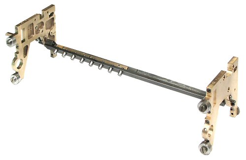
The carriage shift bar.
A cast iron V-section shift bar is mounted between the lower rear sections of the carriage end plates, just below the level of the cross-shafts.
Eight steel rollers are mounted at 20mm centres along the left-hand end of the bar. The rollers are 7mm diameter and 7mm long, and are oriented towards the axis of the camshaft.
 The carriage shift cam.
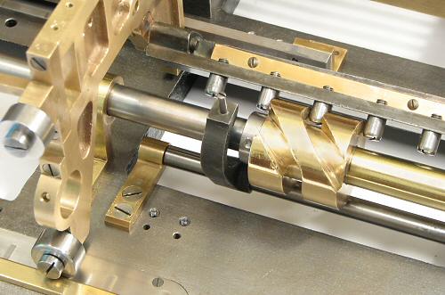
This view shows the left-hand end of the carriage frame, with the shift rollers engaged with the carry shift cam. The single 7mm groove cut around the cam completes a shift in only a quarter of a turn. The mechanism which drives the cam has been described previously.
The camshaft rotates anti-clockwise (as seen from the right), and has just completed a shift movement. As one roller is pushed out on the left, another is drawn in on the right. The carriage is then held firmly in its new position by three rollers as the shift cam completes its rotation.
The shift cam assembly is prevented from moving lengthways by heavy collars pinned to the camshaft at each end. The camshaft itself is restrained laterally by the shoulders and the driving gears at the end bearings.
A locking screw is provided to secure the carriage to the top cover plate during transport.
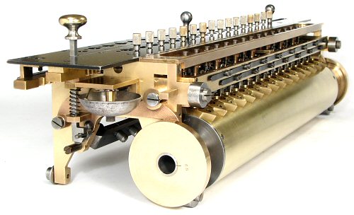 The carriage release mechanism.
The release knob on the left-hand end of the carriage operates through a vertical shaft and a short crank arm to rotate the carriage shift bar through about 45°.
Pressing down on the knob swings the rollers vertically downwards so that they are clear of the shift cam, allowing the carriage to be pushed back to the right.
Care needs to be taken when returning the carriage, as the moving mass is a full 6 kilograms (13 pounds).
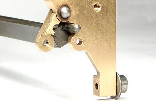 The shift bar hinge.
The carriage shift bar passes under the cross-shafts, and has to be detached from the end plates before the carriage can be removed.
To simplify this operation, the carriage end plates are fitted with split hinges of machined brass. Removing a single screw allows the hinge to be swung open so that the shift bar can drop to the bedplate. One must remember to put it back there before replacing the carriage.
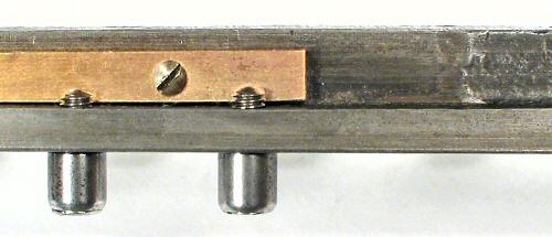 The shift roller retainer.
The shift rollers are attached to the cast-iron bar with shouldered screws. To prevent them coming loose, a 2.5mm end mill has been run between the protruding ends of the screws and the adjacent flange, cutting flats on each. A brass strip has then been pressed and screwed into the gap to hold the roller screws in position.