 Register assembly overview.
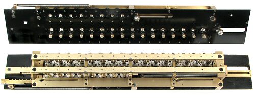
The accumulator and counter registers and their clearing mechanisms form a self-contained sub-assembly that is mounted at the top of the carriage end plates.
The register top plate is made from 2.5mm brass and measures 474 x 73mm. The mechanism behind is about 40mm deep. The completed register assembly weighs 2.4kg and contains over 400 parts.
The right-hand end of the register plate carries an ominous warning notice: "This plate never to be removed". The reason is simply that the registers are best approached from the under side.
Register assembly overview.
The counter register is at the top of the assembly, with the accumulator below. The accumulator dials are fitted with small "twirler" knobs to allow manual setting of initial values for subtraction or division. The larger knobs at the end of each register are pulled to the right to clear the display.
The underside view of the assembly shows the lower support rails, and the slotted plates which guide the clearing racks.
 Numeral dials.
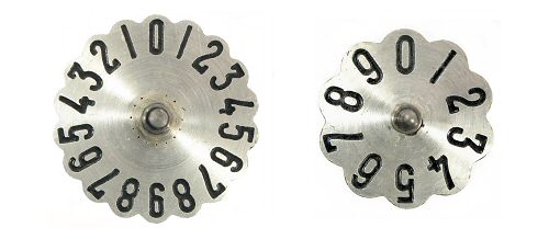
The flat numeral dials are made from 1.5mm brass plate with a traditional clockmaker's silver-white finish. The numerals are recessed and filled with black paint.
The counter dials are 27.5mm diameter and are numbered from 0 to 9 in both directions (18 positions). The accumulator dials are 24mm diameter and are numbered from 0 to 9. Adjacent dials are overlapped vertically to achieve the 20mm column spacing.
The outer edge of the dials is shaped to engage with a detent arm on the underside of the top plate.
 Register detail.
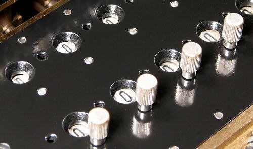
This close-up view shows the top plate with the numeral dials and twirler knobs. The overlapping of the dials can be seen in the peep-hole windows. Alternate peep-holes are drawn deeper to provide a uniform clearance from the dials below.
Small holes are provided between the numeral peep-holes for insertion of decimal point markers. Early machines were supplied with three brass marker pins fitted with red or black handles. Late models replaced the loose pins with fixed rails and sliding metal indicators.
The other holes containing the ends of the counter shafts and the detent arm screws are normally hidden by the machine's top cover plate.
 Register dial assemblies.
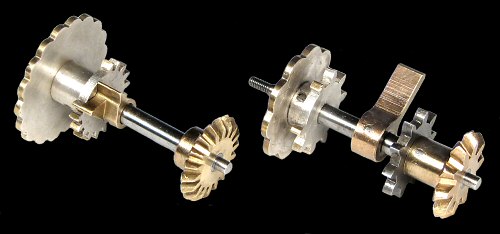
The register dials are assembled on steel shafts of 4mm diameter, reduced to 2.5mm at the plain bearings in the top and bottom plates. The shafts are 40 mm long between the bearings.
The counter assembly (left) consists of the numeral dial, the clearing gear assembly, and the driving bevel gear at the bottom. The components are secured to the shaft with tapered dowel pins.
The accumulator assembly has a simpler clearing gear, but has two additional components - an arm which trips the carry mechanism when the dial passes from 9 to 0 (or 0 to 9), and a steel gear which receives a single increment (or decrement) from the carry mechanism.
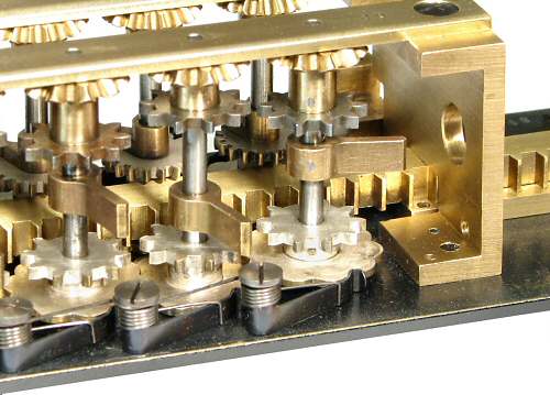 Accumulator detail.
This inverted view shows the left-hand end of the accumulator register, with the counter register behind.
The detent arms and springs are attached to the underside of the top plate. The bottom bearing plate next to the bevel gears travels in the groove between the two sides of the sliding differentials.
The components on alternate shafts are offset vertically to provide clearance. The carry trip arm on the leftmost shaft is set at a different angle to operate an overdraft warning bell (not shown) through the hole in the end bracket.
The accumulator clearing rack is fashioned from a solid length of 6 x 10mm brass. It is supported on slotted guide plates, and extends the full length of the register. The rack is normally held to the right and rearward (in this view) so that it is disengaged from the clearing pinions.
 Accumulator clearing.
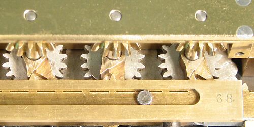
The clearing mechanism uses a long toothed rack and a "mutilated" gear with a missing tooth at the zero position.
To clear the accumulator, the rack is pulled 50mm to the right while the machine is at rest. During the first 5mm the rack is cammed forward by the slots in the guide plates so that it engages with the clearing pinions.
When the dial has been driven back to zero, the rack continues on freely under the missing tooth, and then returns to its home position without affecting the register.
Any tendency for the dial to over-run from 0 to 9 is resisted by the carry mechanism. As the dial reaches zero, the carry trip arm comes into contact with the carry mechanism, in preparation for signalling a 0 to 9 transition. However, the carry mechanism is locked while the machine is at rest, so the trip arm provides a positive stop at zero with no possibility of over-run. (The carry mechanism is described in the next section).
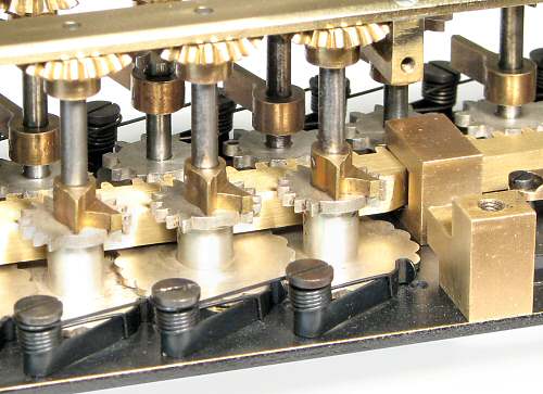 Counter detail.
This view from the opposite side shows the detail of the counter register.
The assembly is rather crowded, with the accumulator clearing rack passing between the number dials and the clearing gears on the counter shafts.
The counter clearing rack is supported in the cutouts in a series of brass mounting blocks. Ramps on the rear surfaces of both racks act as supplementary camming surfaces where they pass through the mounting blocks, to assist the action of the rack guide plates.
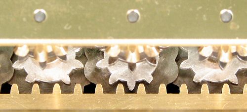
 Counter clearing.
The counter dials have 18 positions rather than 10, and require a finer pitch on the clearing gear. Two teeth must be removed from the gear, and alternate teeth removed from the rack, to allow the rack to move freely past the zero position.
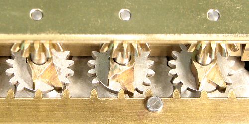
 Counter overrun rack.
There is no carry mechanism to prevent over-run on the counter register, so an alternative must be provided.
A slotted plate with a series of single teeth is mounted on the clearing rack. The plate moves with the rack towards the clearing gears, but is restrained from moving lengthwise by the rack mounting blocks. The teeth provide a positive stop for the small brass arms on the counter shafts.