 The racks.
The drive train operates the reciprocating racks, the tens-carry mechanism, and the controlling camshaft in response to a single turn of the operating crank.
The camshaft makes a single revolution per machine cycle, but the calculating mechanism must make two partial-product cycles to process the tens and units separately.
The racks.
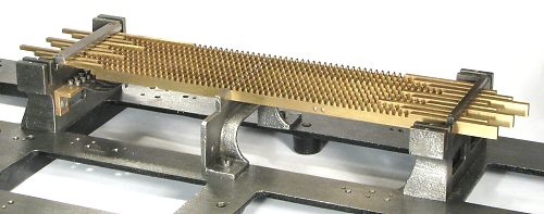
The racks are mounted in slots in three cast-iron support brackets at the centre rear of the machine, and are retained by screwed cover strips. The racks are numbered from 0 at the back to 9 at the front, corresponding to the values set on the sliders or keyboard columns.
The racks are machined from 3.5mm brass plate, and measure 10mm high by 314mm long. The left-hand ends are reduced to 3.5mm in height to engage with the multiplier body. The racks are mounted on 7mm centres, with 3.5mm gaps between.
The teeth on the racks are cut to 4mm pitch over a length of 212mm. As the machine cycles, the racks are pushed from 0 to 9 teeth to the right by the multiplier body, and are then returned to their home positions. A row of leaf springs is mounted on a bracket under the left-hand support to provide a detent at the home (left-most) position.
The zero rack is fixed in position and never moves, but serves to positively lock the cross-shafts when zeros occur in the slider settings.
![]() Rack detail.
Rack detail.
The higher speed of the motor-driven machine apparently caused a problem with the racks being thrown rather than just pushed to the right, leading to over-runs and consequent errors. To counter this tendency, a channel was milled into the rear face of the rack and a spring-steel rubbing strip was rivetted in place. The strip provides an increased friction load where the rack passes through the slots in the centre support.
The rubbing strip is not used in the hand-cranked machines, although the slot to house it is sometimes present.
 The drive train.
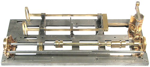
This view shows the components of the drive train, with the rest of the mechanism removed.
The reciprocating brass frame mounted on the rack supports at the rear of the machine is driven from the winding handle through a pair of 1:2 bevel gears and a short crankshaft. The racks are pushed left-to-right by the multiplier body (mounted between the vertical arms at the left) and are returned by the solid crosshead at the right. The rack frame makes two cycles for each full turn of the crank.
The two long shafts across the front of the machine are the camshaft (rear) and the carry drum driveshaft. The camshaft controls the sequencing of the machine operations, and makes one turn for each full cycle. It is driven at 2:1 ratio from the crankshaft by another pair of bevel gears.
The carry drum (described later) makes one full turn for each partial product addition, or two turns per machine cycle. The carry drum shaft is driven at 1:2 ratio from the camshaft through a pair of straight-cut gears at the left-hand end.
 The main drive.
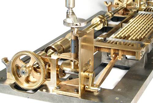
This view from the right-hand rear corner shows the details of the main drive.
There are two separate castings, one supporting the vertical driveshaft, and the other supporting the camshaft and carry shaft bearings. The short horizontal crankshaft has one end in each.
The steel shafts are carried in plain bearings drilled into the castings. The gears and the reciprocating crank are shrunk on to their shafts and are secured with tapered dowel pins. The threaded crank pin is also secured with a tapered dowel to prevent it coming loose. The connecting rod to the crosshead is a substantial bar of solid brass that would not look out-of-place on a locomotive.
There are only minor differences in the drive train between the hand-cranked and the motor-driven machines. The motorised machine has an additional spur gear on the outside of the camshaft bevel gear to receive the drive from the motor mechanism under the bedplate. The winding crank must be unclipped and stowed in the lid (leaving only the knurled knob) so that the motor can drive the mechanism past the stop at the crank's home position. The motor drive runs at 95RPM, but can be disengaged (via a control located near the multiplier lever) when the machine is to be operated manually. Even so, the crank is much harder to turn than on the manual machines, due to the deliberate added friction from the rubbing strips behind the racks.
The extra speed and load of the motor-driven mechanism appear to have taken their toll on this machine at some time in its hundred-year history, as the serial numbers on the main drive castings do not match those on the rest of the machine. One might assume that the plain crankshaft bearings had become so badly worn that a lesser machine was "cannibalised" for replacements.