John Wolff's Web Museum
The Millionaire - Notes on overhaul
There are three schools of though regarding the disassembly of
the Millionaire calculator:
"All parts in this standard machine are interchangeable...
duplicate parts are always on hand in our Melbourne office, and
anyone can fit them in".
(Peacock Bros advertising booklet).
"If you want to take the calculating machine to pieces, please
write for special instructions! (Printed pamphlet)".
(Overprinted in red on the instruction sheet in
the lid of the Millionaire).
"I beg to advise purchasers not to try to take the machine apart
unnecessarily".
(Hans W. Egli, 1907).
The "printed pamphlet" is a 16-page booklet (200 x 135mm) titled
"Directions to follow when the machine is to be taken apart". The
instructions describe removal of the machine from its case, and
disassembly to the point where "any mechanic will be able to take
it completely apart without any further directions". The instructions
are supplemented with a number of line drawings, and an insert with
an illustrated listing of replaceable parts.
The notes following are intended as a similar guide to commencing
disassembly for purposes of cleaning and re-lubrication.
Tools and equipment
The first instruction in the "Directions" is the most difficult:
"First of all procure two good screwdrivers of about 1/8 and 1/4 inch
in width and about 5 inches long". The difficulty is that modern
screwdriver blades are far too thick to fit in the narrow slots of
the Millionaire's hundred-year-old screws. Quality tools should be
selected and ground down to be a close fit. Wear eye protection when
attempting to loosen screws, and be prepared for breakages.
No other tools are needed for partial disassembly, but a full
overhaul will require an ability to deal with tapered pins.
Removal - wooden case
- Set the crank to its home position.
- Tilt the machine onto its back and remove the four large screws
securing the mechanism to the case.
- Roll back to horizontal, remove the large brass screw holding
the lid stay, and support the lid from behind.
- Move the carriage to its central position, then unscrew the
carriage shift knob. Hold the square shaft with a suitable tool if
the knob is tight.
- Remove the 8 screws securing the front section of the top plate
(4 large and 4 small), and lift off the plate.
- Lift the mechanism out of the case. Be prepared for a weight of
30kg (65 pounds), and have a place ready to put it down.
Removal - metal case
- Set the crank to its home position.
- Remove the large brass screw holding the lid stay, and the small
locking screw in the pin of the left-hand hinge. Remove the lid.
- Move the carriage to its central position, then unscrew the
carriage shift knob. Hold the square shaft with a suitable tool if
the knob is tight.
- Remove the 9 screws securing the front section of the top plate
(there is an extra screw in the centre of the lock), and lift off
the plate.
- Lift out the front cover (with the lock).
- Remove the two small screws securing the left and right-hand top
plates to the centres of the side cover plates, then remove the
side plates and lifting handles.
Removing the control panels
- Unscrew the Regulator knob, remove the crank and the multiplier
lever from their square shafts (2 screws), and remove the top plates.
(On the motorised machine, it is also necessary to disconnect the
motor control and interlock mechanisms on the underside of the
multiplier top plate).
- To remove the keyboard, first press the master clear button and
ensure that all the keys have risen. Undo the four securing screws
and lift the mechanism straight up.
- To remove the slider setting mechanism, set the sliders to 2 or 3
and undo the four securing screws. Lift the rear of the unit about
1/2" so that the selector forks are clear of the pinions, move it
rearward so that the numeral wheels are clear of the carriage top
plate, then lift it up and out.
Removing the carriage
- Remove the screws securing the two front corner pillars to the
bedplate. Remove the front pillars complete with their horizontal
cross-bar.
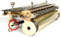 Locate and remove the two lock screws in the carriage shift
bar hinges (circled). The left-hand end has a special long screw.
Open the hinges and press down on the shift control shaft to release
the bar, then lower it onto the bedplate.
Locate and remove the two lock screws in the carriage shift
bar hinges (circled). The left-hand end has a special long screw.
Open the hinges and press down on the shift control shaft to release
the bar, then lower it onto the bedplate.
- With the mechanism in its home position, take note of the timing
marks on the gears at the left-hand end of the camshaft.
- Remove the bearing caps at the outer ends of the long shaft that
passes through the centre of the carry drum.
- Lift the front of the carriage until the shaft is clear of the
bearings, bring it forward until the flanged rollers are clear of
the rear support rails, then lift the carriage (complete with drive
shaft) up and out of the machine.
- Carefully retrieve the carriage shift bar from under the
cross-shafts.
Disassembling the carriage
- Remove the four small screws attaching the carry lever latching
bar to the tops of the carriage end plates, and lift off the bar.
- Remove the two rectangular mounting blocks which carry the top
front support rollers.
- Draw the carry lever assembly forward and out of its bearing
slides and lifting arms.
- Remove the lifting arm on the right-hand end of the carriage.
- Remove the two lower front support rollers to gain access to the
bearing cap screws behind.
- Remove the two half-round bearing caps and remove the carry
drum and shaft.
Points to watch
- A preliminary cleaning before disassembly will reveal a host of
useful numbers, dots, and alignment marks.
- Take careful note of the alignment of the cross-shafts, pinions,
and differentials before disassembly. Square shafts with 10-tooth
gears are not symmetrical. With the rear dial on the zero
detent, the square shaft will have an edge uppermost. The over-run
star wheel and the selector pinion(s) will have a tooth uppermost,
but the differentials will have a gap. See the illustrations in the
Cross-shafts section.
- The pins securing the driving keys in the add/subtract cam and
the carry drum are actually tiny screws.
Original text and images Copyright © John Wolff 2006.
Page created: 19 July 2006.
Next: Patent variations
Back to: Home
Calculating Machines
Hans W Egli
Tech Index
The Millionaire