 Carry mechanism sub-assemblies.
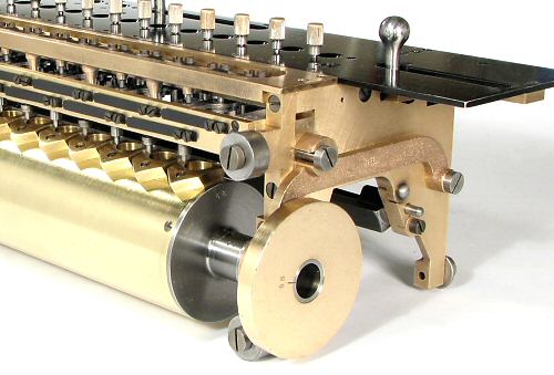
The tens-transfer (or carry) mechanism for the accumulator register occupies the whole of the front section of the moving carriage.
The carry mechanism is a little more complex than usual, in that it must both add and subtract from the adjacent tens column while its driving mechanism only ever rotates in one direction.
This page describes the components of the carry mechanism, and then explains the sequence of operation.
Carry mechanism sub-assemblies.
The carry mechanism consists of three long sub-assemblies which are mounted at the front of the carriage.
In the centre (level with the upper rollers) is the carry lever assembly, which receives the trip signal from the register and returns the carry to the next column.
The brass bar across the top front of the carriage contains a set of vertical spring-loaded pins which latch the carry levers at appropriate times.
At the bottom is the carry drum, which has two sets of cam blocks to operate and then to reset the carry lever mechanism.
The large cam discs at the ends of the carry drum shaft raise and lower the carry lever assembly during the machine cycle, via the horizontal arms on the outside of the end plates.
 The carry levers.
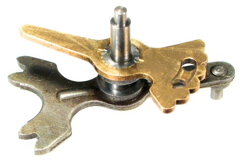
The carry levers consist of a "sensing" arm (top) and an "actuating" arm fixed rigidly to a short 4mm shaft. The lower arm is about 45mm long. The left-hand end (in this view) faces inwards towards the register.
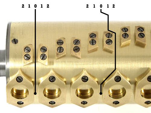
The long tail on the top arm senses the movement of the carry trip arm on the register shaft. The outer end has a 5-position detent, and two holes for the latching pin. The pin normally sits on the recessed web between the two holes.
If a carry (or borrow) is required, the arm will be pushed one position either side of centre, and the latching pin will drop into one of the holes. The pin starts from a position on the recessed area that is already below the top of the hole, so that it will provide a positive stop with no possibility of over-travel.
The "forks" on the lower actuating arm are actually 2-tooth gear segments which drive the carry receiving gears on the register shafts. The pin at the outer end of the lower arm engages with the cam blocks on the carry drum, which supplies the motive force for the carry transfer.
 The carry lever assembly.
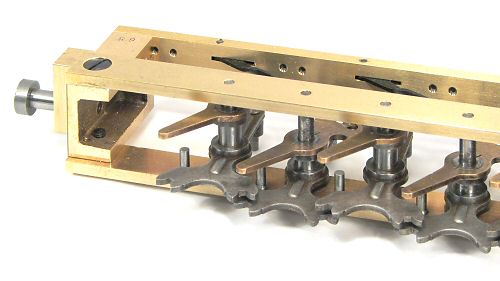
The carry lever assembly is built up from three brass rails and two machined end castings.
The guide blocks on the end castings sit in rectangular housings in the carriage end plates. The whole assembly is raised and lowered +/-2mm by the cam and arm mechanism described above.
The V-shaped detent arms are pivoted in slots in the back rail, with flat leaf springs on the outside (see next illustration).
Stop pins are fitted to the bottom rail to limit the travel of the carry levers.
 Latch pin detail.
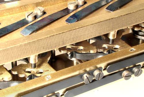
This close-up view of the top front of the carriage shows the carry lever and latch pin assemblies in their normal positions.
The carry lever assembly is raised against the latch pins while the register digits are being advanced (the "digitation" phase), then lowered (as shown) while the carries are being transferred.
The 30 flat leaf springs are each secured with two 1.7 x 4mm machine screws.
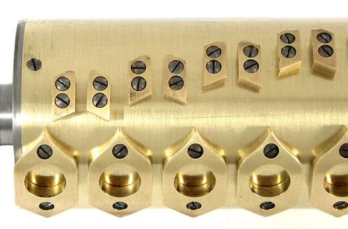 The carry drum.
The carry drum is a hollow brass cylinder, similar to those used in the Swiss music boxes of the period. The drum measures 60mm diameter and 316mm long, with a wall thickness of 1mm.
The drum carries two sets of cam blocks which provide a positive drive for the carry mechanism. The first (staggered) set operates the carry levers in sequence from right to left. The second set returns all the levers to their central position at the end of the machine cycle.
The cam blocks are machined from 5mm brass and are attached with two countersunk screws. The profile of the larger "reset" blocks is curved in three different directions.
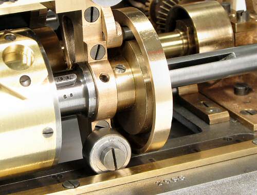 Carry drum drive mechanism.
The ends of the carry drum are fitted with extended steel flanges which are supported in plain bearings in the carriage end plates. The cams which lift the carry lever assembly are attached to the ends of the extended flanges, on the outside of the bearings.
A 12mm diameter drive shaft passes right through the carry drum assembly. The shaft is supported independently in the bearing blocks at either end of the bedplate, and is driven by the gears at the left-hand end.
The drive is transferred to the drum through a long 2.5mm slot cut into the right-hand end of the drive shaft, and a tapered key fitted through the carry drum end flange (between the drum and the bearing).
The flange and the key have been individually hand-fitted, and are stamped with the last two digits of the machine number.
Carry operation.
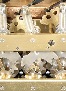
The operation of the carry mechanism is completely hidden when the machine is assembled. The photographs which follow have been taken with the carriage and carry drum removed from the machine, looking vertically upwards at the underside of the accumulator register and the carry levers.
The accumulator lower rail is at the bottom of the pictures. The bevel drive gear, the carry receiving gear, and the carry trip arm are visible in receding order along the register shaft. (Some similar components appear to be different sizes because of their different distances from the camera). The position of the carry trip arms corresponds to the position of the numeral wheels - the arms point to 11 o'clock when the numerals are at zero. The register shafts rotate clockwise for addition when viewed from this direction.
The carry levers are in the upper section of the pictures, with the (reddish) latching bar behind.
This sequence of six stages shows a carry being transferred from the column on the right to its neighbour in the centre.
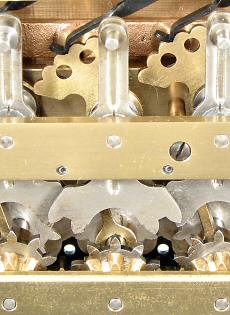
 Stage 1 & 2.
Stage 1 shows the mechanism starting in its cleared position. The register dials are at zero, with their carry trip arms at 11 o'clock. The carry levers are vertical, with their detents in the centre position.
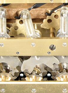
Stage 2 shows the situation during digitation. The carry lever assembly has been lifted (away from the camera) so that the forked carry actuating levers are above and clear of the carry receiving gears on the register shafts. The latch pins are pressing on the webs between the two index holes. The right-hand dial has advanced clockwise to 9, with its carry trip arm now pointing to 10 o'clock. The end of the trip arm is about to contact the (hidden) tail of the carry lever to its left.
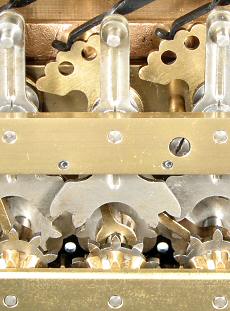
 Stage 3 & 4.
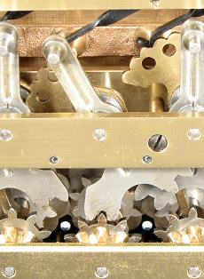
In Stage 3, the right-hand dial has advanced (clockwise) from 9 to zero, with its trip arm now back to 11 o'clock. In the process, the trip arm has pushed the sensing arm of the next carry lever through one step anti-clockwise. The latch pin has dropped into the upper hole to prevent over-travel.
At Stage 4, the digitation phase has been completed and the carry phase commenced. The carry lever assembly drops 4mm (towards the camera), bringing the actuating arm into line with the carry receiving gears on the register shafts. The latch pin is now clear of the hole, but the lever is still held by the detent arm.
 Stage 5 & 6.
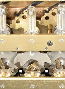
In Stage 5, the cam blocks on the carry drum approach the pins on the outer ends of the actuating arms of the carry levers. If the lever is one step away from centre, the cam block will push it one step further, advancing the numeral wheel by one position. The second tooth on the actuating fork prevents the dial from over-running.
Stage 6 occurs as the (half) cycle ends. The carry lever assembly rises 2mm to disengage the actuating arms from the carry receiving gears, and the carry reset cam blocks return the carry levers to their central positions. The centre numeral dial now stands at 1, with its trip arm pointing to 1 o'clock.
 Carry actuating cams.
This annotated view shows the interaction of the carry lever actuating arms with the cam blocks on the carry drum.
If no carry is required (left diagram), the pin on the actuating arm follows the straight line between the actuating cam blocks and nothing happens.
If the carry lever has been pushed one place to either side during the digitation phase, the corresponding cam block will push it one step further to transfer the carry, and the reset block will return it through two steps to the centre.
The pins remain between the reset cam blocks when the mechanism is in its home position, effectively locking the carry levers in their central position. This prevents an accidental carry trip when setting the dials manually via the twirlers, and also provides a positive stop for the accumulator clearing mechanism (as previously described).