John Wolff's Web Museum
Marchant Figurematic - Overview
The Marchant Figurematic uses a complex and unusual mechanism based
on proportional and differential gearing. Some of its distinguishing
features include:
- Every column of the machine incorporates a ten-speed gearbox
with three drive shafts and five selectors, which drives the
corresponding register dial at a speed proportional to the number
selected.
- The tens-carry mechanism is contained entirely within the main
register in the carriage, using an additive (ie, differential) gearing
mechanism based on two planetary gearsets.
- Multiplier digits are entered on a separate keypad in left-to-right
or as-written order (ie, starting with the most significant). The
calculation is performed "on the fly" and is completed as soon as the
last digit is entered.
- The division mechanism does not wait for overdraft, but uses
a predictive trip mechanism based on an analog magnitude comparator
to avoid unnecessary machine cycles.
- The drive train includes 28 gears on 15 shafts, six dog clutches,
and three different reversing mechanisms. Overall, the machine
contains about four thousand manufactured parts.
- The machine performs a complete addition cycle in less than
one-third of a second, with a peak rate of over one thousand
additions per minute.
This page gives an overview of the layout and construction, and
the basic sequence of operation.
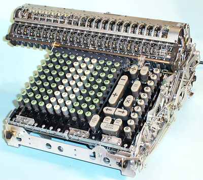 Removing the covers.
The Figurematic covers are held in place by an ingenious system
of overlapping flanges with no visible screws.
To remove the covers, roll the machine onto its back and remove the
four screws in the corners of the base plate. Catch the front panel as
it flies off, and slide the base sideways to disengage it from the
back cover. Loosen the screws in the three small brackets under the
front of the keyboard escutcheon, lift the front of the escutcheon
and pull on the rods at either side to release the rear. Lower the
machine, lift off the back panel, and pull the sides straight off.
Remove the carriage cover from the back with two screws at each end.
Although the space under the numeric keyboard is empty, the rest
of the machine is very densely packed. A few things can be seen to
move as the machine cycles, but on the whole the mechanism reveals
very few clues as to its operation.
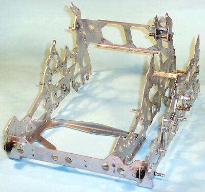 The frame.
With the mechanism removed, we see that the machine is built
upon a substantial pressed-metal frame of 0.078" steel. The frame
plates are held together by interlocking tabs and a generous quantity
of 3/16" bolts. A rear base plate (not shown) supports the drive
motor. There are four smaller sub-frame plates in the control unit
area on the right of the machine.
The frame sits on a light pressed-metal base plate with an
absorbent lining. The side covers are substantial aluminium die
castings which are located by the rubber grommets at each corner
of the frame.
The calculating mechanism is built up from a number of separate
modules which are supported by the frame. Although the mechanism
looks impenetrable on first aquaintance, there is actually very
little holding it together. The major modules can be removed and
replaced relatively easily, once you know how they are connected.
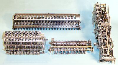 The main modules.
The mechanism consists of four main modules:
- the carriage (rear), which contains the counter register,
the main accumulator register, and the carry mechanism.
- the control unit (right), which contains the drive train
and the mechanical control logic.
- the selector unit (front left), which sets up the gear
ratios in each column according to the input from the keyboard.
(The selector unit also houses the division trip mechanism).
- the actuator unit (front centre), which contains the
proportional gearing that drives the main register.
There are three other modules which are not shown in this view - the
keyboard columns, the setting camshaft, and the drive motor and
electricals. Each of the modules is described in more detail in the
sections following.
Basic sequence of operation.
At its most basic level, the mechanism operates on a four-stage
cycle:
- Manual setting. Pressing a numeral key positions a
"selection cam" near the bottom of the selector unit, and a check dial
(the "keyboard dial") near the top.
- Powered setting. Pressing a function key releases the
setting clutch and starts the motor. The setting clutch rotates the
setting camshaft (the "setting line") exactly half a turn, and then
disengages. The setting line operates the selector mechanism, which
sets up and locks the gear ratio for each column according to the
position of its selection cam, and "dips" the carriage to bring the
main register into engagement with the actuator.
- Addition. As the setting line comes to a stop, it engages
the main clutch to drive the actuator unit, which in turn drives the
register columns via the selected gear ratios. The drive passes
through a reversing mechanism for subtraction or division.
The main clutch rotates either:
- half a turn for a single addition cycle
- a known number of half-turns for multiplication
- an (as-yet) unknown number of half-turns for division.
- Restore. On completion of the main clutch cycles, the
setting clutch re-engages and completes another half-turn, raising the
carriage and restoring the machine to its original state in readiness
for a new operation.
(Note: when the Marchant manual speaks of "opening" or
"releasing" a clutch, it means releasing the dog which
stops the clutch, thus engaging the drive).
Original text and images Copyright © John Wolff 2005.
Page created: 2 February 2005. Last Updated: 2 May 2005.
Next: The keyboard
Back to: Home
Calculating Machines
Full-keyboard Rotary Calculators
Marchant
Tech Index
Marchant Figurematic