 The multiplier keyboard.
The Marchant Figurematic does not have a separate multiplier storage register, but performs the multiplication "on the fly" as each digit is entered on a separate keyboard at the far right of the machine.
The first factor is set on the main keyboard, then the digits of the second factor are entered one at a time on the multiplier keyboard. After each keypress the machine makes the required number of additions, and moves the carriage one place to the left.
The multiplier digits are entered in left-to-right or "as written" order, starting with the most significant. The process must begin with the carriage a sufficient distance to the right, rather than (the more usual) fully to the left. The "Clear/Return" key and tabulator are used to set the starting position.
The "count-back" mechanism which controls the number of additions is in two parts - a setting mechanism driven by the multiplier keyboard and the setting shaft, and a count-and-trip mechanism driven by the main clutch.
The multiplication cycle takes from 320mS for 1, up to 800mS for 9. Successive digits can be entered as soon as the setting cycle is complete (140mS), giving the impression of continuous operation.
The multiplier keyboard.
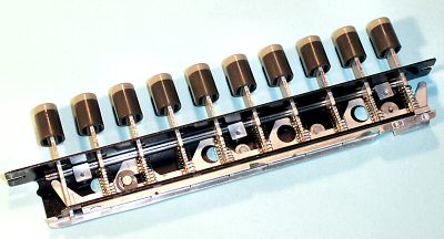
The multiplier keyboard is a single row of ten keys at the far right of the machine. The "sawtooth" link prevents adjacent keys being pressed down together. A sliding locking plate locks and releases the keyboard at appropriate times as the cycle progresses.
The keystems act as stops for a sliding link which sets the count-back mechanism, and also press down on a "parallel bar" linkage which controls the motor and interlocks. (Except for the Zero key, which simply initiates a carriage shift into the next column).
 Multiplier component overview.
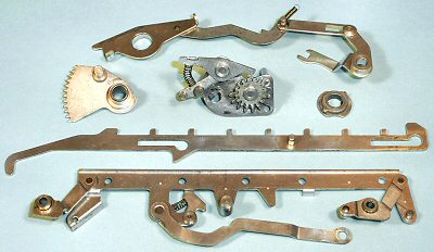
This view shows the main components of the multiplier mechanism.
Pressing any multiplier key (except zero) operates the parallel bar (bottom) and related linkages. This starts the motor and engages the setting clutch via a ratchet or "kick" mechanism on the outside of the No. 3 gear.
While the normal actuator setting process is taking place, a multiplier setting arm (not shown) pulls the sliding link forward until one of the tabs on its upper surface strikes against the lowered keystem. The long hook at the end of the sliding link pulls on the pin on the gear sector, rotating the count-back gear (centre) to the corresponding position.
The two-tooth return gear (centre right) is attached to the main clutch, and drives the sector backwards by one tooth for each addition cycle. When the sector returns to its home position it pushes on the trip linkage (top) to release the roller latch and stop the cycle.
There is extensive interlocking to prevent mis-operation, and a "single-cycle" mechanism to ensure that the multiplication will not be repeated if the key is held down.
 The multiplier setting linkage.
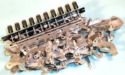
This view shows the inner sub-assembly of the control unit with part of the multiplier linkage assembled on the nearer side. The parallel bar, sliding link, and gear sector are readily visible.
More multiplier control links, levers, and interlocks are assembled on the inside of the outer right-hand side plate, and then the two sides are brought together. Very little of the multiplier mechanism is visible when the machine is fully assembled.
 The count-back gear.
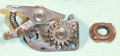
The count-back gear is mounted on the outer right-hand side plate, just forward of the main clutch. (The half-round hole secures the end of the main clutch shaft).
The gear is driven backwards by the cam-and-tooth assembly on the right. The notched cam allows the detent to rise momentarily as the single tooth passes, rotating the mechanism by one position for each addition cycle.
The mechanism is driven "off the end" of the 10-tooth partial gear as it reaches its home position, and so has no effect when the main clutch rotates in subsequent calculations.
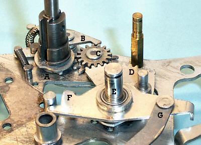 The trip mechanism.
This "underneath" view shows the trip mechanism assembled on the inside of the outer right-hand side plate.
The gear sector D pivots on shaft E, and is pulled forward (right) during the setting cycle by the pin on its right-hand side. The setting is held by the detent B. The cam A on the main clutch shaft raises the detent as the single tooth drives the count-back gear C one tooth per addition cycle.
As the sector is driven into its home position, its left-hand edge presses downwards on the tab F on the horizontal trip lever. This pulls upwards on the connecting link G, releasing the roller latch and stopping the main clutch. The machine then performs a restore cycle, shifts the carriage, and comes to rest.