 The main gears.
The drive train provides the motive power for the selector unit, the actuator, the counter register, and the carriage shift and clear mechanisms.
It contains 28 gears on 15 shafts, six dog clutches, and three reversing mechanisms. The drive mechanism is mounted at the rear of the control unit on the right-hand side of the machine.
The drive train is powered by a series-wound universal motor governed at 3000RPM.
The main gears.
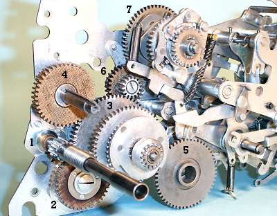
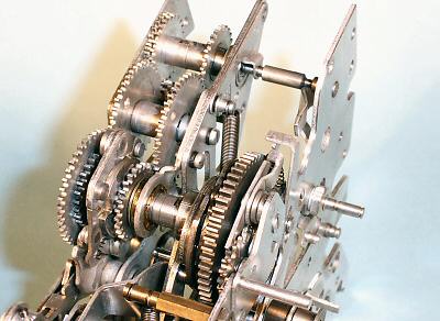
This view shows the main drive gears, partially assembled on the inside of the outer right-hand side plate. A separate sub-frame plate is installed later to support the inner ends of the shafts.
1. The motor shaft and primary drive gear. The gear is
driven through a safety clutch (removed for clarity) on the threaded
section of the shaft.
2. A pair of fibre and steel reduction gears. The mounting
provides for adjustment relative to the motor shaft.
3. Number 3 shaft carries two large drive gears, the
carriage shift clutch and drive gear, and two small shift reversing
gears.
4. A fibre gear which drives three carriage clearing
clutches on the keyed shaft.
5. Number 5 gear is the final drive to the setting clutch.
It is mounted on the setting shaft in the bottom of the machine, and
driven from the second gear on the number 3 shaft.
6. A pair of steel and fibre intermediate gears.
7. The final drive to the main clutch and actuator unit.
The motor, number 3 shaft, and the main clutch rotate clockwise when viewed from the outer right-hand side of the machine. The setting line and the clearing clutches rotate anti-clockwise.
 The main clutch components.
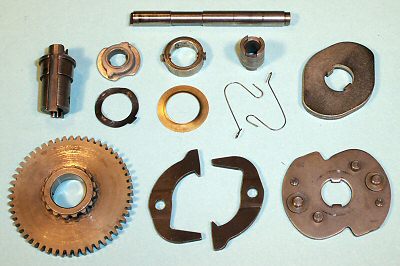
The bottom row shows the main clutch drive gear and splines, the driving pawls, and the driven plate. The top row shows the bushings and retainers, the pawl springs, and the locking cam.
The drive pawls are spring-loaded so that their inward-facing teeth engage with the splines on the hub of the drive gear. The clutch is normally held disengaged by a release dog which drops into one of the notches in the outside of the driven plate. This forces the tail of the drive pawl inwards, raising its inner end clear of the splines. The tail of each pawl presses and slides against the head of the other, so that the two pawls always move in and out together.
There are two notches in the driven plate, so the clutch will advance half a turn at each operation.
 The main clutch installed.
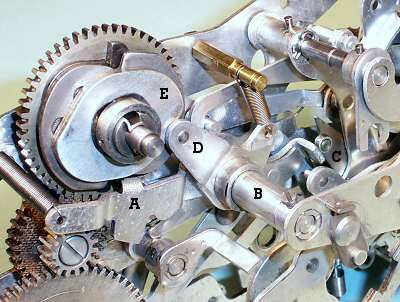
This view shows the main clutch installed with its shaft and bushing on the right-hand side plate.
The main clutch release dog A is pivoted on shaft B and held upwards by the spring at its left-hand (rear) end. The forward end of the release dog rests on a small but very important "roller latch" C (centre right).
The release dog is flicked downwards via a cam on the setting shaft at the end of the setting phase, and is caught and held by the roller latch as the clutch rotates. When the latch is released (by the control mechanism after the required number of cycles, or immediately for a single addition), the release dog rides on the outside of the driven plate until it drops into the notch, lifting the pawls and removing the drive. A roller on spring-loaded arm D presses inwards on the locking cam E and wedges the driven plate firmly into its home position.
All of the driving clutches work on the same principle, although they differ in their internal details and their operating and locking mechanisms.
 The reverse clutch.
Subtraction and division are accomplished by reversing the main drive to the actuator unit. The reversing mechanism, or "reverse clutch", is mounted inboard of the main clutch on the same shaft.
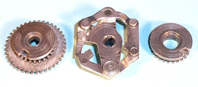
The central plate is driven directly by the main clutch. The surrounding 4-bar linkage can be rocked left or right to engage one or other of the dogs on the lower link with the gears on either side of the plate.
If the left-hand gear is engaged, the drive proceeds immediately to the large output gear and thence to the actuator unit. If the right-hand gear is selected, the drive proceeds via a large double idler assembly and a reversing idler to drive the left-hand gears in the opposite direction.
 The reverse clutch installed.
This view shows the main and reverse clutches (front) and the double idler gear (centre) at the rear of the control unit. The reversing idler is hidden under the central support bracket. The gears behind the double idler provide another reversible drive mechanism, which operates the counter register whenever the main clutch rotates.
The reverse clutch dogs are operated by a rocking lever mounted below the clutch. The control unit selects addition or subtraction by positioning an interposer under one side or other of the rocking arm. During the setting cycle, a "reverse cam" on the setting shaft raises the interposer and pushes the arm and the clutch dogs into the required position.
 The setting line.
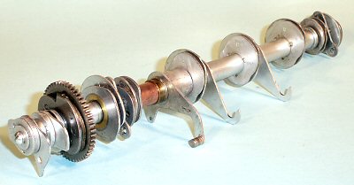
The setting shaft is a double-keyed steel shaft 0.405" diameter and just over 10" long (the full width of the machine). It is driven from the No.3 shaft via a drive gear and half-turn clutch which are the same as those in the main clutch. The shaft carries eight single cams, six double or opposing cams, and about twenty spacers, shims, and other components. The complete assembly can be removed and replaced as a unit (after a certain amount of practice).
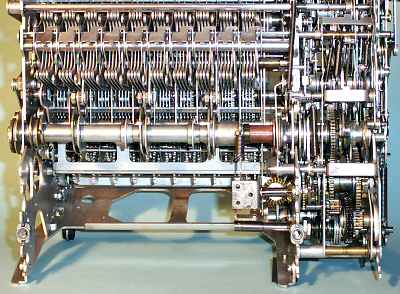 The setting line installed.
In this view the machine is standing on its back to show the underneath. The motor base plate is not yet installed. The setting line is in the centre, with the selector mechanism above and the selection locking bail below.
The setting line makes a full revolution, in two stages, for every machine cycle. The first stage is triggered by the operator pressing a function key. The setting clutch is released, and the shaft rotates half a turn to perform the setting phase. Just before it stops, it trips the main clutch release dog. The machine then performs addition cycles until the control unit releases the roller latch. As the main clutch release dog rises and stops the main clutch, it trips the setting clutch again to commence the second half-turn for the restore cycle.
 The motor assembly.
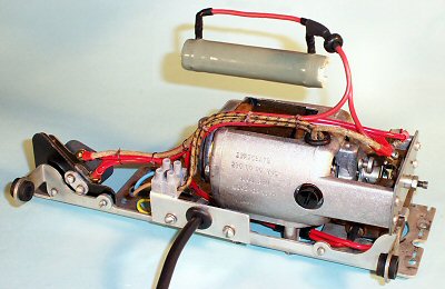
The motor and electrical equipment form another self-contained module which is mounted on a base plate at the rear of the machine. The drive motor is a General Electric universal motor which is governed at 3000RPM. The power switch is at the left, and the suppression capacitor is under the motor. The governor resistor is wound on a ceramic tube and covered with vitreous enamel, and can get very hot after sustained use. It is mounted above the motor, on the inside of the rear frame plate.
In the interests of electrical safety, the original cloth and rubber wiring has been replaced with high-temperature plastic, and the custom 2-pin power connector has been replaced with a fixed lead and a secure earth connection. There are still exposed live terminals on the motor and the power switch. Extreme care must be taken if power is applied with the covers removed, as the machine does not meet modern safety standards.
The motor speed of 3000RPM is reduced about 14:1 for the setting line and 6:1 for the main clutch. The setting cycle requires 6 turns of the motor shaft and takes 120 milliseconds (120mS). Each half-turn of the main clutch takes only 3 turns of the motor (60mS), and the restore cycle takes about 7 turns (140mS). The setting cycle appears shorter than the restore because the main clutch starts slightly before the setting cycle has finished.
A complete addition operation (set, add, restore) takes 120 + 60 + 140 = 320mS, while a multiplication by 9 takes 120 + (9x60) + 140 = 800mS. The repeated additions during multiplication and division proceed at a peak rate of about one thousand additions per minute, or seventeen cycles per second.