 The drive shafts.
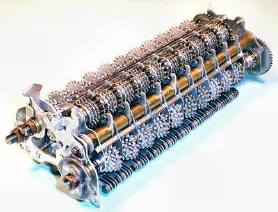
The actuator unit contains the proportional gearing mechanism which drives the main accumulator register in the carriage. Each of the ten identical sections contains a ten-speed gearbox with eleven ratio gears, fourteen transfer gears, and five two-way selector arms. The unit is mounted between the main side plates at the upper rear of the machine, immediately below the carriage.
The drive shafts.
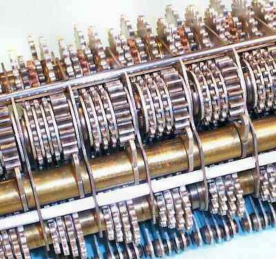
The actuator unit has three drive shafts in the lower section which carry the ratio gears, and a single output shaft at the top. The three drive shafts carry a total of 110 gears, which are driven simultaneously from the main clutch via the single large gear at the right-hand end. The output shaft carries ten compound gear assemblies which transfer the rotation of the selected ratio gears to the main register in the carriage.
The main clutch rotates the front ratio shaft exactly half a turn for each addition. The upper rear shaft is driven from the half-turn shaft via a 2:1 reduction gear at the right-hand end. This in turn drives the lower rear shaft via a 3:1 reduction at the left-hand end. The three drive shafts thus rotate 1/2, 1/4, and 1/12th of a turn for each addition cycle. The "centraliser cam" at the left-hand end has a double spring-loaded detent to hold the shaft securely in its home position at the end of each cycle. A "hold-off" mechanism disables the centraliser during repeated cycles.
The drive shafts and gears can be adjusted laterally by springs and nuts at the left-hand end. The actuator unit on its own is not particularly rigid, and relies on the frame plates for accurate positioning and alignment. The "arrow head" at the upper left-hand end is not related to the gear mechanism, but serves to align the carriage laterally as it is pulled down ito engagement with the actuator.
 The ratio gears.
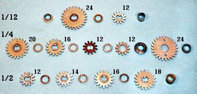
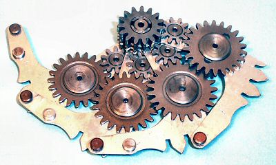
This view shows the ratio gears for one section of the actuator, arranged in order as they are assembled on the three drive shafts.
Rather than thinking of ratios, it is easier to consider the distance that each gear advances during an addition cycle. The rightmost gear on the front shaft has 18 teeth, and so will advance by 9 positions for each half-turn cycle. This movement can be "picked up" and transferred to the output gear to advance the register by 9 digits. Likewise for the 16, 14, and 12-tooth gears.
The three leftmost gears on the quarter-turn shaft have 20, 16, and 12 teeth, and deal with digits 5, 4, and 3 in the same manner. The sequence can not be continued for digits 2 and 1, as it is impractical to make an 8 or 4-tooth gear. Rather, 24 and 12-tooth gears are provided on the twelfth-turn shaft. Their movements are copied back onto the quarter-turn shaft through 12 and 24-tooth idlers, to be picked up by the transfer mechanism.
 The ratio gears assembled.
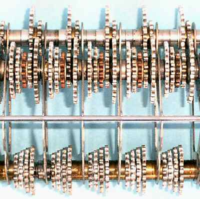
This top view of the actuator unit shows the alignment of the ratio gears on the three drive shafts. The output is picked up from the pairs of gears on the half and quarter-turn shafts as shown:
| 1/4-turn | 5 | 4 | 3 | 2 | 1 |
| 1/2-turn | 6 | 7 | 8 | 9 | 0 |
(There is no gear for the Zero position on the half-turn shaft).
 The pick-up arms.
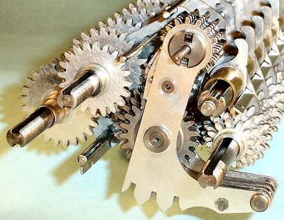
This view shows the actuator unit partially assembled, as seen from the left-hand end. The pick-up arms hang from the output gear assembly at the top of the unit. The flanged pins at the bottom front of the arms engage with forked yokes on corresponding arms on the selector unit.
As the setting line operates, one of the five arms will be swung forward or back by the selector forks. The other four arms will remain in "neutral". The selection will be locked by a bail that rises into the slots at the bottom of the arms.
The large "pick-up" gear on the active arm will engage with the corresponding ratio gear on either the half or quarter-turn shaft. As the shafts rotate, the pick-up gear drives through an intermediate gear (hidden) to the output gear at the top, and thence to the carriage register.
The output gear is normally locked in known positions by the detent arm on the large keyed shaft at the centre right, thus ensuring that the pick-up gears and the register will always engage cleanly.
 The pick-up gear assembly.
In this view the pick-up gear assembly has been spread open to show the internal construction.
Four of the five selector arms are permanently assembled with their pick-up gears, idler gears, and output gears. The fifth arm is mounted face-down on the top (to the right, as installed), and shares the double-width output gear, which also drives the register.
All of the output gears are keyed together, so that all of the transfer gears will rotate in unison. As the active selector drives "up" the gear train, the four neutral selectors drive back down, spinning their pick-up gears in mid-air.
 The output gears.
This view from the top front shows how the four sections of the output gears are interleaved with the tops of the five pick-up arms. The centre-to-centre distance of the columns is 5/8", so each pick-up arm with its gears and rivetted hubs has to fit into only 0.090".
In order to transfer the motion from the actuator to the display, the accumulator register is pulled downwards (or "dipped") to engage with the output gears. At the same time, the detents in the register are released as they are pulled down against the rod mounted at the top of the actuator (just behind the output gears). The continuous gear train from the main clutch to the register dial ensures that the numeral wheels are precisely controlled for the whole of the addition cycle, allowing the detents to be disengaged to reduce friction and noise. The gear train rotates in a positive, smooth, and silent operation with no possibility of overrun.
If Zero is selected, the right-hand pick-up arm moves forward and holds the actuator detent arm against the output gear, keeping it locked as the other columns are released. The broad keyway in the detent shaft (see photo 4 above) provides about 10° free movement to allow the detents to move independently.