 Overview.
The main register, otherwise known as the "accumulator" or "middle dial", consists of 20 identical sections which "accumulate" the inputs from the actuator unit.
The carry mechanism differs from most others in that it operates continuously, rather than in discrete steps. If the units dial advances to 5, the tens dial will advance to 0.5 and the hundreds to 0.05. A "correction" mechanism temporarily hides these additional increments before the result is displayed.
The register mechanism uses two planetary or "epicyclic" gearsets in every column. One gearset adds the inputs from the actuator and the (partial) carries from the previous column, and the other subtracts the correction for display.
The register also includes a sensing mechanism which provides one of the inputs to the division trip comparator in the selector unit.
This page describes the components and the construction of the main register, and then explains the operation of the gearsets.
 Overview.
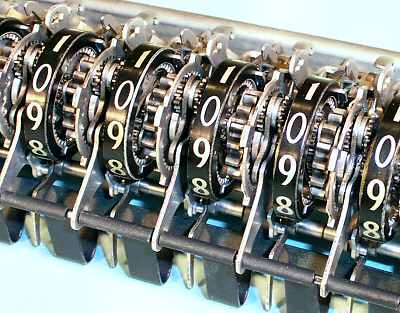
This view of part of the assembled register shows something of the density and complexity, but (like most of the Marchant mechanism) it gives very few clues as to its operation.
The components are shown individually in the next illustration.
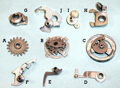 The main register components.
A. The idler gear, which receives the input from the actuator
unit when the register is pulled down into engagement ("into the dip").
B. The main planetary gearset, driven by idler A and
the input from the previous column.
C. The numeral wheel and snail cam. The numeral wheel is
driven by gearset B, and drives the next column via the small
central pinion.
D. The sensing arm. The roller near the centre of the arm
rests on the snail cam, and rises proportional to the number displayed.
E. The sensing finger, operated by the pin on the end of
D, which communicates the numeral wheel position to the
division trip mechanism.
F. The backstop and latch, used only during the clearing
of the register.
G. The clearing cam, double-keyed to the clearing shaft at
the rear of the register.
H. The detent arm, which engages with the idler gear
A. The detent is raised by the clearing cam G, or by
the rod above the transfer gears on the actuator unit when the
register is dipped.
I. The inter-stage gear and carrier, which also functions
as the planet gear for the "correction" mechanism.
J. The correction quadrant, which rotates the inter-stage
gear carrier to apply the correction to the display. The quadrant
also provides the clearing function. The operation of the quadrant
is controlled by the two tabs at the bottom which engage with the
sensing arm Dand the detent arm H, and also by the
"tail" at its upper left which engages with a fixed rod through
the frame of the upper register.
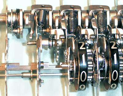 The register assembly.
The left-hand column shows the clearing cam and detent arm assembled on the 1/4" clearing shaft at the rear of the register.
In the next column there are four components assembled on the 5/64" (0.078") intermediate shaft. The sensing arm and backstop are installed on the left, and the idler gear and correction quadrant on the right.
In the third column, the register gearsets have been installed on the 1/16" pivot shaft at the front. A temporary locking rod (under the zero) keeps the gears in position until all the columns have been assembled.
 Epicyclic or planetary gearing.
An epicyclic or planetary gearset consists of one or more "planet" gears P, attached to some sort of frame or "carrier", which can revolve around a central "sun" gear S. The planets are surrounded by an "annulus" or "ring gear" R which has the gear teeth on its inner surface.
The planetary gearset can provide three fixed gear ratios if one or other of the three members is held stationary, or it can add or subtract inputs from any two members to drive the third.
Consider the planet carrier to be held stationary. If the sun gear rotates forward, the ring gear will rotate rearward in the ratio S/R (where S and R are the numbers of teeth on the sun gear and the ring gear). If the sun gear is held stationary and the planet carrier is rotated forward, the ring gear will rotate forward in the ratio (1 + S/R). If both sun and planets are driven independently, the movement of the ring gear will be the sum (or difference) of the individual contributions.
Similar ratios can be calculated if the ring gear is held stationary. The ratios and directions are not always intuitive, especially with more complex gearsets.
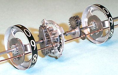 The gear train.
This exploded view shows the gear train components spread out along the shaft.
The small pinion on the right-hand numeral wheel forms the sun gear for the first planetary gearset. The inter-stage gear is the (single) planet, and the ring gear is attached to the main planetary gearset (centre).
The main gearset adds the inputs from the actuator (via the large-toothed input gear) and the previous column (via the ring gear) and sends the total via the double planet gears to the ring gear on the left-hand numeral wheel.
The locking wire (front) holds the numeral wheels, the central ring gear, and the two planet carriers in their home positions during assembly.
 Main register gearing.
This diagram shows the technical details of the two planetary gearsets that are illustrated above.
A is the numeral wheel of the first (or any) column, which is fixed to sun gear B of 10 teeth. B drives through the inter-stage planet gear C-E (15 teeth) and its carrier D to the central ring gear G (40 teeth). (The planet gear is split into two parts to pass over the frame plate F, but functions as one). With the planet carrier stationary, there is a 4:1 (40:10) reduction between the numeral wheel A and the ring gear G.
Ring gear G is fixed to the second sun gear H of 16 teeth. H drives through the planets I (12 teeth) and carrier J to the second numeral wheel L (40 teeth). With the planet carrier stationary, there is a 5:2 (40:16) reduction between the central ring gear G and the left-hand numeral wheel L. The overall ratio between the two numeral wheels is thus (4:1 x 5:2), which is 20:2 or 10:1 as required.
The input from the actuator is applied (via the idler gear) to the drive gear K of 14 teeth, which is fixed to the second planet carrier J. Recall that the actuator transfer gear advances by one tooth for each digit position. Thus it is required that a 10-tooth advance of 14-tooth gear K should advance the numeral wheel L by one full revolution (ie, an increased rotation). With the sun gear H held stationary, the ratio between the planet carrier and the numeral wheel ring gear is (1 + 16/40), which is 56:40 or 14:10 as required.
The resultant motion of the left-hand numeral wheel L is thus the sum of these two movements, ie, one digit position per actuator tooth in the current column, plus one-tenth of the rotation of the previous numeral wheel.
 The "correction" mechanism.
The correction mechanism uses the inter-stage gear and quadrant to temporarily subtract the increment due to the previous column before presenting the display. The correction is applied as the register rises at the end of the addition, and is removed at the start of the next operation.
This view shows how the quadrant engages with a positioning gear on the back of the planet carrier, allowing the carrier to be rotated through a quarter of a turn.
The "tail" on the rear of the quadrant normally sits above a fixed rod in the upper section of the register assembly. As the main register is pulled down "into the dip" to commence an addition, the tail is held up by the rod. The relative motion lifts all the tails (relative to the rest of the register), and rotates all of the planet carriers to the fully rearward (vertical) position. The addition then proceeds as described above, with the planet carriers stationary.
When the register rises, the tail of the quadrant falls, allowing the planet carrier to rotate forward. The gearing is such that a rotation of one-quarter of a turn on the planet carrier will reduce the next numeral wheel display by one digit. The motion is limited by a tab on the bottom of the quadrant, which lifts the sensing arm until its roller strikes against the snail cam. The correction is thus proportional to the previous digit position.
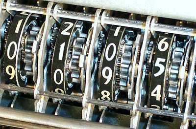 Addition stage 1.
This view shows the register displaying "0095" part-way through an addition cycle, before the register rises and applies the corrections. This state is never visible during normal operation.
The register is still dipped, and the inter-stage planets are all pulled back to their "home" positions with their carriers vertical (visible to the left of the uppermost numerals).
The units column stands at 5, as expected. The tens column has been advanced by 9 places by the actuator, plus a further 0.5 of a place carried in from the units column. The hundreds column has advanced to 0.95 of a place by the carry alone, and even the thousands column has moved by almost one-tenth (0.095) of a place.
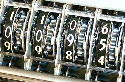 Addition stage 2.
As the register rises, the quadrants allow the planet carriers to move forward until stopped by the sensing arm and snail cam. A 90° rotation of the carrier will reduce the next numeral display by one place.
The units digit stands at 5, so its sensing arm rises half way. (The tip of the sensing arm is visible to the left of numeral 4). The planet carrier rotates 45° (to the left of numeral 5), subtracting 0.5 of a place from the tens digit.
The tens digit now stands at 9, so its sensing arm lifts further (visible to the left of numeral 8). The planet carrier moves further forward (to the left of numeral 9) and corrects the hundreds display. The process continues across the register, temporarily storing the "excess" corrections in the positions of the inter-stage planet gears.
Addition stage 3.
If we now add another 5, the carriage first goes back into dip and restores the situation shown in Stage 1. The units digit advances from 5 to 0, the tens from 0.95 to 0, the hundreds from 0.095 of a place to numeral 1, and the thousands from 0.095 of a place to 0.1 of a place.
As the register rises, the units and tens digits already stand at 0, so no corrections are applied to the tens and hundreds. The hundreds digit stands at 1, and applies a correction of one-tenth of a place to the thousands. The end result is a display of 0100, as expected.
Ripple carry.
If 1 is subtracted from a cleared register, the display must change to all-nines. The subtraction proceeds as normal, with the actuator driving the units digit back one place to 9, and the inter-stage gearing driving the tens backwards by 0.1 of a place.
As the register rises, most of the numeral wheels and snail cams still stand at 0 and prevent the sensing arms from rising. The units digit stands at 9, and so begins to subtract a correction of 0.9 of a place from the tens digit. In moving the tens back from 0 to 9, the high point of the snail cam moves out from under the sensing roller. The roller immediately rises, allowing the correction quadrant to move back and the planet carrier to move fully forwards, reducing the next digit by one place from 0 to 9. The process repeats as a ripple carry across the whole register, with the energy being provided by the correction quadrant springs.
If 1 is added to all-nines, the result must return to all-zeros. As the carriage dips, the correction quadrants pull the planet carriers back to their home position and restore the register to the state in the first paragraph. (The energy is provided by the carriage pull-down mechanism working against the quadrant springs). Adding 1 then returns the two right-hand digits to zero, so no corrections are needed as the register rises.
 Clearing the register.
This view from the rear of the register shows the components involved in the clearing operation.
Prior to clearing, the register is in a state similar to "Addition Stage 2" above, with the inter-stage planet gears some distance forward of their home positions.
As the clearing shaft (bottom) rotates about 15° it raises the idler gear detent (lower centre) and pushes the backstop (centre) forward against the central ring gear. As it moves another 15°, a lug on the bottom of the detent arm raises the rear of the correction quadrant, pulling the inter-stage gears back towards their home position.
The planet gear will initially tend to pull the central ring gear rearwards as well, but this movement is blocked by the backstop as soon as the ring gear reaches its home position.
With the ring gear held stationary, the 4:1 reduction ratio now operates in reverse, spinning the previous numeral wheel rapidly backwards. As the displayed numeral reaches 0, the tab between numerals 2 and 3 strikes the horizontal section of the backstop and is caught by the spring-loaded latch. Clearing of each column depends to some extent on its neighbours, and the whole operation relies on speed and inertia to throw the numeral wheels back under the latches.
As the clearing shaft is released, the quadrant and planet gear will be held in their home positions by the sensing arm resting against the high (zero) point of the snail cam. Finally, the backstop is released, and the detent arm re-engages to lock the input gear.