Contents

Contents |
|
| 20ATG with Triplex carriage |
This page gives detailed procedures for removing and replacing the Triplex carriage on the Madas ATG and BTG machines.
Removing the carriage is quite straightforward. Replacing it is rather more complicated, as there are a lot of things to get right. This page describes the various mechanisms involved, and explains how they must be set for a successful installation. The final section summarises the process in a step-by-step procedure. The whole operation of refitting the carriage can generally be done in about 10 seconds - after a bit of practice.
 Fig. 1. Removing the carriage
Identify the small carriage release lever indicated by the red circle. On a few late-model machines the lever is hidden under the window plate surrounding the keyboard register RIII. The plate is easily removed (2 screws) when necessary.
Clear the registers, and move the carriage to position 3 or 4. Disengage Register IV by setting the I/I+IV lever (at the left of the red circle) to the forward position.
From the back of the machine, remove the two screws in the upper section of the rear cover, just below the carriage. Ease the cover off its dowel pins and remove.
Stand in front of the machine and take a firm grip of the carriage at each end. Be careful not to lean on the multiplier bar. With your left thumb, press the carriage release lever (circled red) towards the front of the machine, then lift the carriage straight up and out (ie, perpendicular to the keyboard).
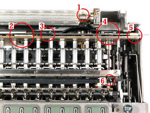 Fig. 2. Points of interest
This view of the right-hand rear section of the machine shows the
general location of the "points of interest" that are important in
replacing the carriage. These are described in more detail below.
1. RIV drum gear timing marks
2. Carriage sensing rack centre bearing
3. Carriage sensing rack positioning lugs
4. Carriage shifting disc and pins
5. Carriage rack outer bearing
6. RIV reversing link.
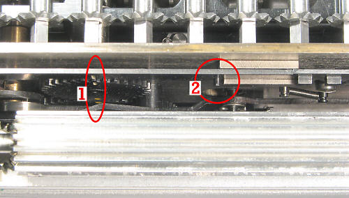 Fig. 3. The carriage sensing rack
The long rack across the rear of the machine senses the carriage position and communicates it to the multiplier unit.
From the front of the machine, push the rack to the left into its home position, with its right-hand end flush with the outside of its outer bearing.
From the rear (as illustrated), note that there are two sets of timing marks (1) on the gear that engages with the rack. The straight lines on the gear and the rack must match when the rack is in its home position. On the diametrically opposite side of the gear is a dot, which aligns with a dot on the larger gear below. All four marks should be in a straight line.
If you have removed the carriage in order to carry out other repairs to the machine, it may be best to remove the rack now to avoid damage to its unprotected ends. Proceed as follows:
- Remove the small screw holding the rack outer bearing. Ease the bearing off its dowel pins and slide it off the rack.
- Lift the outer-bearing end of the rack so that it is clear of the gear, then slide it to your right until the stop pin (2) meets the centre bearing. Then lift and slide further so that the pin behind the rack comes free of the centre bearing and the rack can be removed.
Reverse the procedure to refit the rack, taking note of the timing lines and dots. Do not rotate the gears indiscriminately with the rack removed, as it may take many revolutions to get the dots back into alignment.
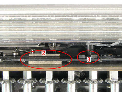 Fig. 4. Positioning the sensing rack
The two square lugs (3) on the rear face of the sensing rack engage with a similar lug on the underside of the carriage, so that the rack will follow the carriage movement in both directions.
Before the carriage can be fitted, the lugs must be correctly positioned relative to the carriage shifting mechanism, so that both mechanisms can be engaged simultaneously.
The easiest method is to move the rack to an (approximately) central position (carriage positions 3 to 5), and then set it so that any pair of the small round pins on the front of the rack (at the ends of red oval 2) are located as shown relative to the centre bearing. Note that there is a slightly larger gap to the pin on the right-hand side.
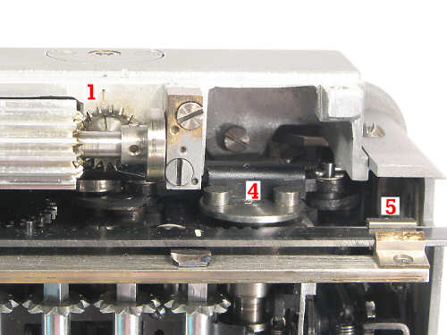 Fig. 5. Positioning the RIV drum gear
The drum gear at the rear of the machine drives the RIV camshaft in the carriage, and must be timed correctly. The timing marks (1) on the bevel gear and frame must align when the carriage is fitted and the mechanism is in its home position.
The drum gear will usually be rotated slightly during engagement as the carriage is lowered into position, so it is best to start with the mark on the gear slightly to the left. Turn the drum gear rearwards by hand until it sits just on the edge of the detent.
This view also shows the carriage shifting disc and pins (4), which engage with the shifting rack in the carriage. The disc rotates half a turn for each carriage position. The sensing rack and its outer bearing are shown at (5).
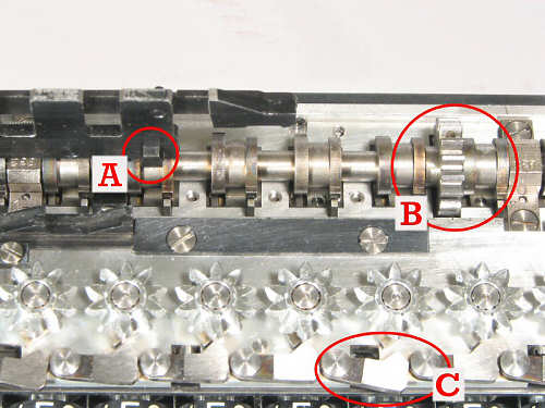 Fig. 6. Under the Triplex carriage
At the far upper left of this picture are two of the large square teeth of the carriage shifting rack, which engage with the pins on the shifter disc (Fig. 5 above, item 4). The innermost tooth of the shifting rack has a square pin (A) on its inside face. This pin fits between the two lugs on the sensing rack (Fig. 4, item 3).
Note the location of the square pin relative to the shifting rack tooth, as it is not visible when trying to engage it with the sensing rack. It may help to mark a white line on the rear of the rack tooth, in line with the pin, and to paint the edges of the receiving lugs to make them more visible.
The RIV camshaft and driving gear are shown at (B). The camshaft runs the full width of the carriage.
The row of small hinged pawls at (C) serve two purposes: they are pushed outwards to transfer a carry request to the carry levers in the main body of the machine as the accumulator dials pass from 0 to 9, and they are drawn inwards to act as stops as the dials are spun backwards to 0 during clearing. They must be held inwards during installation, or they will rest on the tops of the carry levers and prevent the carriage being properly seated.
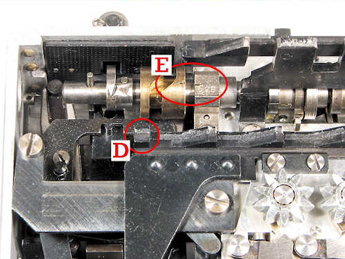 Fig. 7. Positioning the carry pawls and RIV camshaft
The two adjacent sawtooth racks extending to the right from (D) engage with the clearing arm at the right of the machine in order to clear the accumulator and counter registers. In refitting the carriage, the accumulator rack is pulled and held outwards, thus holding the pawls inwards and clear of the carry levers. In practice, the two adjacent racks are pulled out together. Some folk use a loop of string or wire around teeth (D), but it is easier done directly with a finger under the carriage. The registers should be cleared first to reduce the force required.
Note the timing marks (E) on the RIV camshaft bearing and the adjacent brass cam. Turn the camshaft via the gear at the other end until the marks are aligned exactly. It is helpful (but not necessary) to make a tool to turn the camshaft and to indicate its position while the carriage is in place. A pin is provided for this purpose near the end of the camshaft, with a matching access hole in the end of the carriage.
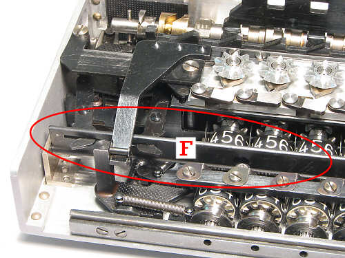 Fig. 8. The RIV reversing bail
Register IV can be set to follow RI in either direct or complement mode, but must still reverse when RI reverses. As the RI differential gears slide fore and aft to select addition or subtraction, the movement is communicated into the carriage through the RIV reversing bail (the hinged vertical bar at F), which operates the RIV reversing mechanism in the end of the carriage.
The two links projecting through the left-hand end of the bail position a selection lever to either side of the pointed cam near the end of the RIV camshaft. If the RIV clutch is engaged, the adjacent brass cam then operates a sliding link to set RIV for direct or complement addition. Otherwise RIV remains in neutral.
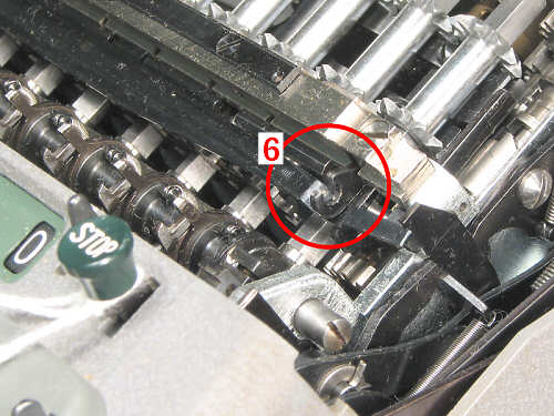 Fig. 9. Engaging the RIV reversing bail
The RIV reversing bail in the carriage engages with a small forked arm protruding from the front of the carry lever detent bar at the right-hand rear of the machine.
The arm passes freely through a slot in the detent bar and connects to the positioning plate under the differentials. Slide the differentials forward by hand to put the fork into an accessible location.
Having examined and understood the mechanisms involved, you are now ready to install the carriage. There are three stages: preparation, installation, and checking. Proceed as follows: