 The keyboard.
The main function of the keyboard mechanism is to translate the vertical movement of the selected key into a corresponding movement of the segment lever and the accumulator pinion. The keyboard mechanism must position the 12" segment lever with an accuracy of far better than half a gear tooth (0.075" pitch) if the machine is to operate reliably. The Comptometer uses an ingenious "key stop" mechanism to ensure that the motion is precisely controlled with no possibility of over-run.
The keyboard mechanism also includes some auxilliary functions which are used in the error-correction and zero-signal mechanisms. These are illustrated below as they arise, but the detailed descriptions are left for the sections following.
The keyboard.
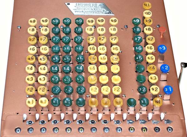
The "full" keyboard has a key for every digit in every column, except that there are no zero keys.
The octagonal keytops are marked with the corresponding number, and with its complement for use in subtraction. The odd-numbered rows have more deeply recessed keytops, with the columns colour-coded by value. The darker columns on the Model J are green; those on the Model H were black. The keytops are moulded onto the keystems and can not be removed without destruction.
The clearing handle (right) is pulled lightly forward and released to clear the register. The small red button at the top right resets the "controlled key" mechanism (described later).
The pattern of wear on these keytops shows that the 3 and 4 keys were by far the most used. Comptometer operators found it less tiring to make repeated keystrokes near the "home" position (the 3 row) than to move their whole arm to reach the higher keys.
 The decimal indicators.
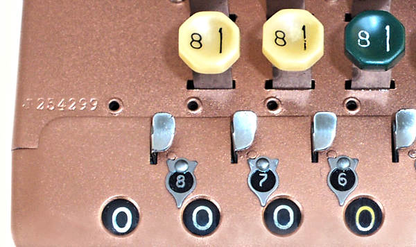
This close-up view shows four more examples of the quality and attention to detail that are found throughout the Comptometer:
The serial number is stamped at the left-hand front of the key plate, and on the left-hand frame support plate inside.
 The keys.
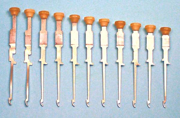
This view shows the keys from the pence column of a Sterling Comptometer. The 10 and 11 keys (on the left) have additional curves and cut-outs to clear the mechanism at the rear of the machine.
The key stems are made from 0.067" steel, with the decimal keys ranging from 4" to 4-3/4" long. The key travel averages 1/2", varying from 13/32" for the "1" keys to 19/32" for the nines.
The broad (3/8") section near the top of the key acts as a bearing surface where it passes through a slot in the key plate at the top of the machine. The two lugs or shoulders near the centre of the key engage with the levers to operate the mechanism. The narrow tail of the key passes down through the levers, and the hook at the bottom engages with a spring-loaded retainer in the underside of the machine. The shoulder just above the bottom hook acts as an upwards key stop, but there is no downwards mechanical stop on the keys themselves.
 The keypieces.
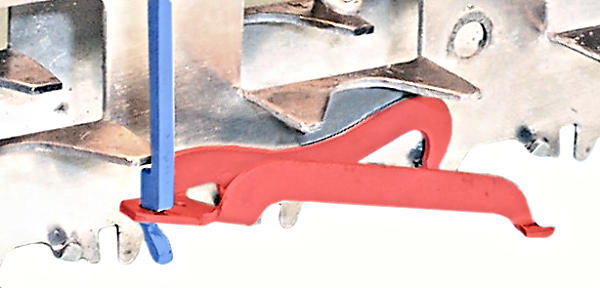
The key stems are supported by spring-loaded retainers or "key pieces" (red) mounted between the frame plates at the bottom of the machine. The "V"-shaped key pieces are about 1-3/4" long, with the hook on the keystem (blue) passing through a hole in a flattened section at the apex. The "feet" at the broad end fit into matching slots along the lower edge of the frame plates.
The spring (not fitted in this view) pushes the key piece and keystem upwards, so that the shoulder on the keystem (just above the hook) rests against the large "M"-shaped section folded horizontally from the frame plate.
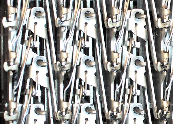 The keypieces from underneath.
This view shows the keypieces and springs from underneath. The bottom edges of the frame plates have a series of shallow rectangular slots to hold the "feet" of the keypieces, and an adjacent folded tab to hold the tail of the torsion spring. The spring keeps the left-hand foot firmly in position, but tends to twist and raise the right. This is resisted by overlapping the feet in adjacent columns, so that the left foot of each keypiece holds down the right foot of its neighbour. (Hence there is a full column of "un-used" keypieces in the ten-shilling and farthings columns, just to hold down the adjacent columns. The rightmost column uses a folded tab arrangement to secure the right-hand feet).
The keypiece springs are sometimes graduated by row to compensate for the varying leverage. Typically the 1 and 2 springs may use 0.033" wire diameter compared to 0.027" elsewhere, but other arrangements may be found.
The keypieces have to be tilted sideways to fit over the hook on the keystem, but once installed the keys can not escape.
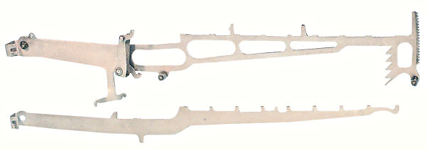 The segment lever and the lock lever.
The lock lever (lower) is an auxilliary lever which works in conjunction with the segment lever and the keys to arm the "controlled key" mechanism (described later).
The lock lever is pressed from 0.035" sheet and is 11-1/4" long. It lies alongside the segment lever for its full length, but is shaped to minimise friction through metal-to-metal contact. The upper horizontal sections of both levers rest at the same level, but the key tabs on the lock lever stand higher than those on the segment lever. The "extra" tab near the centre of the horizontal section is pulled up against a stop wire to set the rest position.
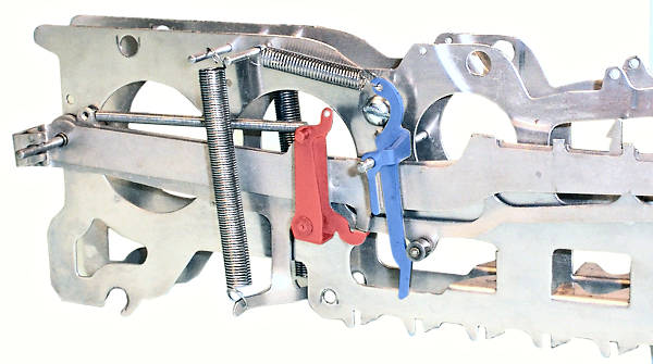 The bell crank and brake lever.
This view shows the lock lever nested inside the segment lever on the 0.108" pivot wire at the rear of the machine.
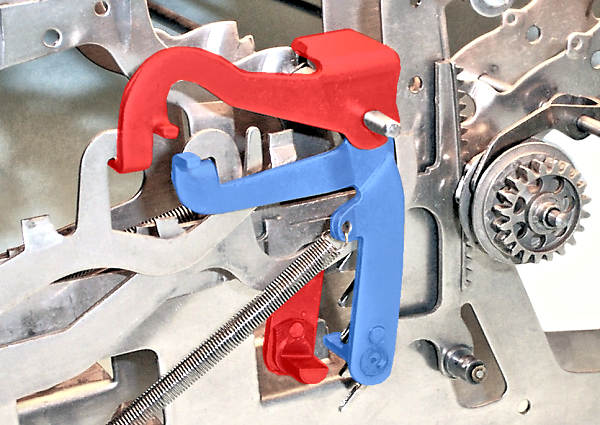
Just forward of the main spring is the segment lever bell crank (red). The bell crank is mounted on a pivot attached to the segment lever, and is pulled rearwards by a long horizontal coil spring. The short forward arm at the bottom of the bell crank supports a tab on the bottom of the lock lever, and holds the lock lever upwards against the stop wire located between the 5 and 6 keys. Relative motion between the segment and lock levers will cause the top of the bell crank to move forward or back (described further in the "Controlled Key" section).
Forward of the bell crank is the brake lever (blue), pressed from heavy (0.067") sheet and mounted on another 0.108" pivot wire. The brake lever has a heavy horizontal spring on its upper arm, which presses the lower arm forward against a 0.220" OD roller on the segment lever. The tail of the brake is shaped so as to be pushed rearward against the spring tension when the segment lever first begins to move down, giving an initial over-centre feel to the key stroke.
The brake lever and its roller provide a frictional load which helps to control the speed of the segment lever as the main springs pull it upwards on the return stroke. The lower tail of the brake lever also operates an auxilliary mechanism (described later) to engage the rock frame on the first keystroke of a new calculation.
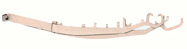 The key stop levers.
The key stop levers are a second pair of full-length nested levers which lie parallel to the segment and lock levers in each column. The levers are pressed from 0.035" sheet, and are pivoted just above the segment lever at the rear of the machine. The inner (closer) lever has operating tabs for the even-numbered keys, and the other for the odd keys.
In spite of the name, the key stop levers do not stop the keys. Rather, the key stop levers operate the key stops, which stop the segment lever, which stops the keys.
 The key stops.
The key stops are a pair of heavy (0.067") "inverted-L" levers which operate alternately for the odd and even keys. The key stops are nested together on a 0.108" pivot wire, one on each side of the sawtooth rack near the front of the segment lever.
The vertical arms of the key stops are pulled rearwards by long coil springs attached to the frame plates. The horizontal arms support the forward ends of the long key stop levers, via the "inverted-J" hooks.
The actual "stops" are a pair of half-round lugs which are securely riveted to the bottom of the two vertical arms. As the key stop lever is presssed down, the corresponding vertical arm swings forward to engage the stop lug with the saw-tooth rack, bringing the segment lever to a very positive stop.
The "odd" keystop (blue) is shown forward and engaged with the sawtooth, so as to reveal the "even" stop (red) in more detail. Note how the even key stop folds over behind the frame plate to engage the sawtooth from the far side.
 Key operation - rest position.
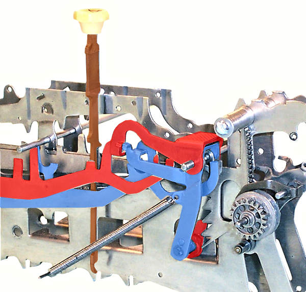
The keys are normally supported by a keypiece at the bottom, and located by a slot in the key plate at the top. The key plate rests directly on the top horizontal edges of the frame plates.
The four long horizontal levers are shown in their rest position. The keystem passes between the levers, with the segment lever and lock levers on the far side and the key stop levers closest.
The vertical arms of the key stops are pulled rearwards, so that the stop lugs are clear of the sawtooth rack. The horizontal arms are held upwards, supporting the key stop levers. The extended vertical tabs on the two key stop levers are pushed upwards against the horizontal stop wire (just rearward of the keystem), thus setting the rest position of the entire key stop mechanism. The lock lever is held upwards against the same wire by the segment lever bell crank and spring. The segment lever is held upwards against the eccentric cam on the front tie rod.
As the key starts to move down, the shoulder on its right-hand side first contacts the tab on the lock lever, which stands slightly higher than that on the segment lever. The relative motion between the two levers operates the segment lever bell crank, pushing its vertical arm forward and arming the "Controlled Key" mechanism (described later). As soon as the key reaches the segment lever tab the two levers move down together and the bell crank movement ceases.
The key continues downwards, with the backstop holding the accumulator and the pinion ratchet free-wheeling.
 Key operation - full stroke.
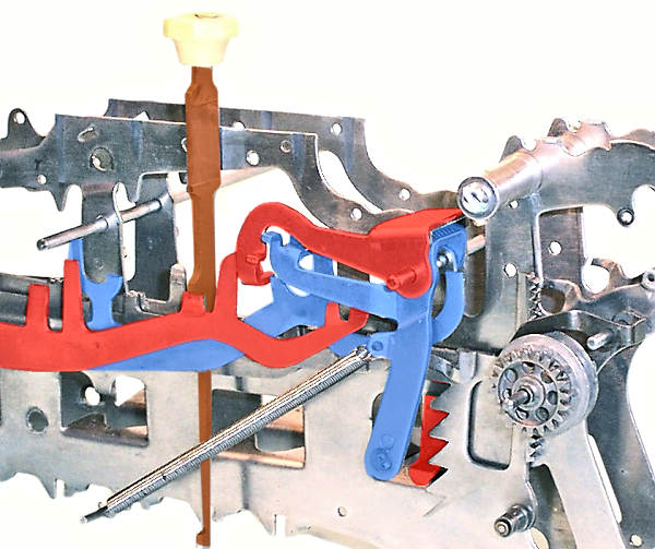
As the key reaches the bottom of its intended travel, the shoulder on its left-hand side contacts the raised tab on the corresponding key stop lever and pushes it downwards. (The key shown is number 4, which engages with the even key stop lever. Notice that the other lever is still pulled up against the central stop rod).
The key stop lever presses downwards on the horizontal arm of the key stop, swinging the vertical arm forward into the path of the sawtooth rack on the segment lever. All motion comes to an abrupt and positive stop when the lower horizontal surface of the downward-moving sawtooth collides with the upper horizontal surface of the forward-moving stop lug.
The heights of the tabs on the keystems and the key stop levers are arranged so that the keys will operate the stops alternately on the five horizontal sections of the saw-tooth rack - 1 and 2 on the lowest section, 3 and 4 (shown) on the second section, and so on.
The final position of the segment rack (and hence the accumulator pinion) is very precisely controlled, as it depends only on the dimensions of the sawtooth rack and the length of the key stop arm, and not on the keys or the lever mechanism.
When the operator releases the key, the segment lever springs pull the mechanism back to the starting position, with the pinion ratchet advancing the accumulator by an exact number of steps.