 The Comptometer case.
The Comptometer case.
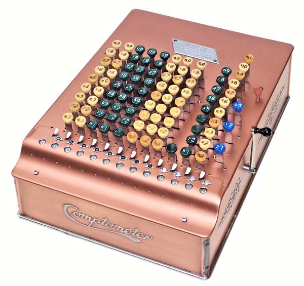
The distinctive case of the Model J Comptometer is built up from a number of separate panels:
The base, sides, and top are lined with sheets of linoleum about 3/16" thick to absorb both sound and oil. (Linoleum is a rubberised cork compound with a hessian backing, widely used as a floor covering in the days before sheet vinyl).
The steel panels are copper plated and lacquered to give a rich "metallic" finish. The Comptometer logo and scrollwork are embossed into the side panels and either blackened or polished to a contrasting finish. A 12-column case alone weighs over 7 pounds, before any of the mechanism is added.
 Removing the case.
To separate the mechanism from its case, first remove the numeral wheel cover and the clearing handle, then invert the machine and set it down on the keys on a soft towel. (Do not roll it over, as this can break the keytops). Remove the four countersunk screws near the corners of the base, carefully separate the sides from the keyplate, then lift the base and sides straight up.
The mechanism is a close fit inside the case, and will probably be stuck to the linoleum in several places.
It is not necessary (or helpful) to remove the screws in the keyplate or the corner pillars, and one should never attempt to remove the keytops.
 The Comptometer mechanism.
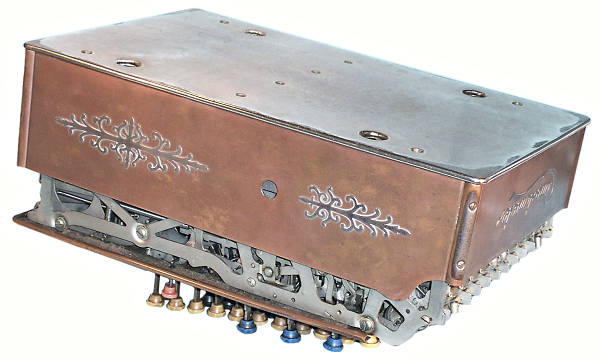
Even when removed from its case, the Comptometer retains its rather monolithic appearance and reveals very little of its inner workings.
At this stage we will engage the services of the workshop fairies to disassemble and clean the mechanism (over a thousand parts and sub-assemblies, comprising well over 2500 manufactured parts), so that we can re-build the machine "from the ground up" and study its construction and operation.
A detailed step-by-step procedure for disassembly and reassembly is provided seperately. It will make much more sense after we know how it all works.
 The frame.
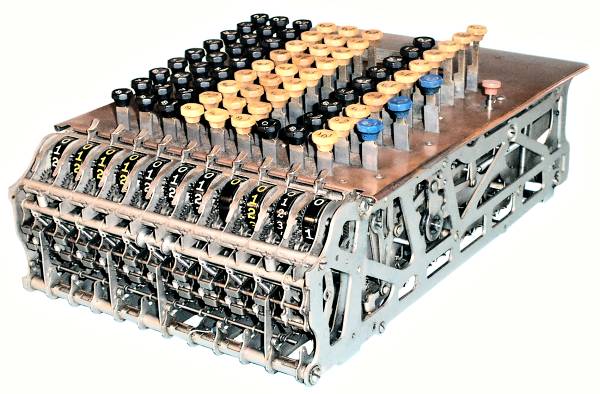
The frame of the Comptometer is built up from a series of complex and rather elegant frame plates measuring 14" x 4" (approx) and pressed from 0.037" steel. The plates are supported by ten cross-shafts or tie rods (5 x 0.227" dia, 5 x 0.155" dia), and are held at just under 3/4" separation (0.742" centres) by rolled or pressed sheet-metal spacers on each of the shafts.
The mechanism is built up between the side plates as a series of more-or-less identical columns. The components of the mechanism are supported on a total of 30 wires or shafts that pass crosswise through, above, or under all of the plates. The support wires vary from 0.055" to 0.108" diameter.
Although the frame plates are basically similar, they vary in the detail of their attachments (rock frame toggles, keyplate bushings, Sterling gearsets, etc). There are 14 plates in this 12-column machine, and 11 of them are different.
The spacers are mostly 0.705" wide. There are special spacers adjacent to the linoleum guards and the keyplate clips, and shortened spacers next to the internal feet. U-shaped shims are also fitted where necessary. Detailed records need to be taken if the frame is to be disassembled.
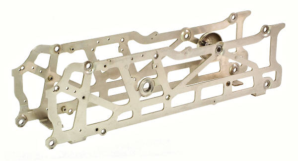 The frame support plates.
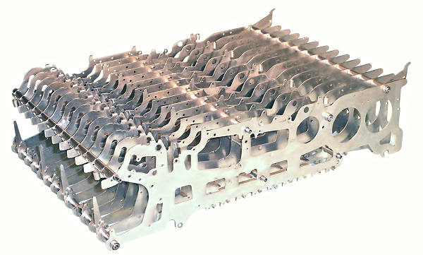
The frame is mounted between a pair of heavy truss-like support plates pressed from 0.084" steel. The tie rods enter the corresponding holes in the support plates to provide a positive location. Tightening the screws in each tie rod pulls the side plates and spacers tightly together to provide a very stiff and rigid assembly.
Shims are fitted where necessary to maintain clearances as the tie rods are pulled up tight. Four of the five larger tie rods have a special threaded spacer nut behind the right-hand support plate, so that the support plate can be loosened or removed without disturbing the rest of the frame.
The "zero-signal" bell is visible near the back of the left-hand support plate. The clearing handle attaches to the boss near the centre of the right-hand plate. The "feet" under each plate secure the whole assembly into the case. The serial number is stamped into the "tail" at the top rear of the left-hand support plate, as well as into the keyplate near the leftmost "1" key.
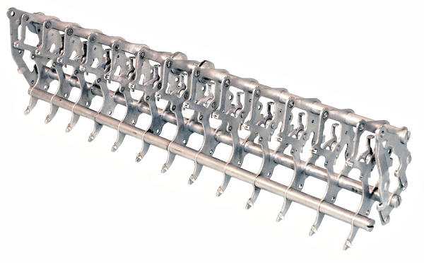 The "Rock Frame"
The "Rock Frame" is a major sub-assembly which mounts in the gap at the lower front of the main frame. It is constructed in the same fashion, with a series of identical frame plates, three tie rods, and tubular spacers. Part of the carry mechanism ( the carry lever locking dog, described later) is permanently riveted to each rock frame plate. The rock frame has its owm serial number, stamped into the right-hand end plate.
The rock frame houses part of the gear train and the carry mechanism, and "rocks" forward during clearing to disengage the gears and allow the numerals to return to zero.
The case and frame to this stage contain over 600 manufactured parts.