John Wolff's Web Museum
Rebuilding the Model 3D11 Comptometer
Contents
|
|
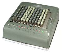
| Comptometer 3D11, c.1955 |
Introduction
These notes give a detailed step-by-step procedure for a complete
disassembly, reassembly, and adjustment of the Felt & Tarrant Model 3D11
manually-operated Comptometer. A separate procedure is provided for
rebuilding the earlier Model J. Readers with a Model H should use the
Model J procedure; those with a Model M or WM should adapt the relevant
sections from each procedure.
The notes have been prepared and refined during the rebuilding of
a significant number of Felt & Tarrant machines of various types.
There are no particular difficulties in rebuilding a Comptometer, and
there is no requirement for workshop facilities or special tools.
However it does require patience, care, and attention to detail. The
procedure following works well for me, but comes with no guarantees.
No responsibility will be taken for any consequences arising from
the use of these notes by others.
The notes are intended to be read in conjunction with the
Technical Description of the Model J
Comptometer, and with the more general information in the
Notes on overhauling a mechanical
calculator. The Technical Description explains the construction
and operation of the basic Comptometer mechanism and illustrates all of
the major components and assemblies, while the Notes on Overhaul describe
more general techniques for disassembly, cleaning, and rebuilding. Please
study this material carefully before commencing your overhaul, and
refer back frequently for the illustrations as you proceed.
I would be happy to receive feedback, comments, or suggestions via
the enquiry form.
Disassembly
Disassembly does not require any special tools, although a good
pair of bent-nose tweezers or fine pliers will be found useful. Except
where advised otherwise, it is strongly recomended that you keep the
parts in column order during disassembly and cleaning. The extra time
taken will be saved many times over by avoiding trouble in reassembly
and adjustment. Accumulators, for example, were selected in the factory
according to the angular (mis-)alignment between the pinion and the
accumulator gear, and may cause significant problems if paired
incorrectly. Keeping columns together is especially important in
non-decimal machines, where many similar components have small
differences but big incompatibilities.
A Comptometer can be disassembled to frame level in about 3 to 4
hours if no problems are encountered. A thoroughly gummed cross-shaft
can take 4 hours on its own.
Please review the material in the
Notes on overhauling a mechanical
calculator, and proceed as follows:
- Preliminaries
- Print a copy of these notes, and tick off each step as it is
completed.
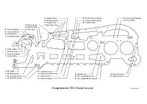
- Print the
frame plate outline drawing (PDF file, 64kb) to show the location
of the 33 mechanism cross-shafts.
- Prepare a set of numbered bags or containers to receive the parts
in column order, and to store the cleaned parts. Column 1 is on the
right. Prepare containers labelled A to K to receive the frame
tie rods, spacers, and shims.
- Unscrew and remove the top of the clearing handle. Pull off the
error release button (front) and the Mul/Div button (left). The
buttons are retained by spring-loaded ball catches which may be
stuck or rusted.
- Stand the machine on its left-hand side and remove the small
screws around the edge of the baseplate. Some of these screws will
probably be missing, as they tend to work loose and fall out. Set
the machine back on its feet and lift off the cover.
- Invert the machine and set the keys down on a soft cloth. Do not
roll it over, as this can break the keytops. Remove the 4 screws
through the rubber feet and lift the baseplate away from the mechanism.
Set the machine back on its internal feet.
- Remove the cross-shaft retainer plates (metal or fibre-board)
from the sides of the mechanism (3 screws each side).
- The rock frame.
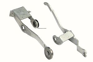
- Clear the machine. From the right-hand side, push the intermediate
gear shaft 7 to the left to clear the shutter actuating lever in the
rightmost column (shown on the left in the photo opposite), but not so
far as to release the intermediate gear. The shutter actuating lever
has a long invisible arm on the left-hand side with a roller at the
bottom. Tilt the lever so that the roller moves rearwards, then
upwards, then forward, then lift it out in front of the hub of the
intermediate gear. If the roller catches on the carry gear and will
not move upwards, it can be released by turning the numeral wheel
slightly.
- Withdraw shaft 7 further and drop the intermediate gear down into
the space between the large carry gear and the frame plate to its
right. The top of the gear should be just below the top of the rock
frame plate.
- Lift out the subtraction cutoff latch release lever (on the right
in the photo). The top end of this lever is hidden between the numeral
wheel and the frame plate to its right. The lower end has a fork which
fits over a wire in the rock frame, just below its top spacer rod.
Pull the bridge of the lever forward, ease the top arm past the
shutter operating tab, and lift out.
- Repeat the process in the remaining columns. Insert a short
temporary pin (eg the shank of a 7/64" drill) at the right-hand end
to support the rock frame as wire 7 is withdrawn. Leave wire 7 in place
to support the frame at the left-hand side. (If you have the
facilities, it is convenient to make up a couple of short temporary
pins of 7/64" (0.108") diameter to support the rock frame during
removal and reinstallation).
- Release the clip at the right-hand end of the rock frame toggle
pivot wire 4. Pull the rock frame forward, withdraw the wire to the
right, and recover the helper springs.
- Press any key to release the detaining toggle. Lift the front of
the machine and remove the support wire 3 which passes through the
slots in the rock frame actuating links. Pull the rock frame forward
and disengage the forked links from the pins on the rock frame plates.
Place a suitable block under the front of the machine so as not to
damage the links when putting the machine back down.
-
 Support the rock frame with one hand and remove wire 7 and the
temporary pin. Hold the rock frame at each end, lift it straight up as
far as it will go, and pull it forwards to clear the duplex levers.
Rotate the frame until the two locating flanges (top centre) are clear
of the main frame plates, then push it across to the right. The
movement is only about 1mm, just enough for the toggle levers to
clear the toggle link rivets. Sit the leftmost escapement lever over
the toggle link mounting point, as illustrated, then swing the top of
the rock frame forward so that it passes under the top spacer bar E.
Lift out carefully to avoid catching on the carry levers. Although it
may seem impossible at first, the rock frame can actually be removed
and replaced quite easily after a bit of practice (and you'll get
plenty of practice by the time you've finished). It is never necessary
to use force, to remove the tie rod, or to modify any part of the
machine.
Support the rock frame with one hand and remove wire 7 and the
temporary pin. Hold the rock frame at each end, lift it straight up as
far as it will go, and pull it forwards to clear the duplex levers.
Rotate the frame until the two locating flanges (top centre) are clear
of the main frame plates, then push it across to the right. The
movement is only about 1mm, just enough for the toggle levers to
clear the toggle link rivets. Sit the leftmost escapement lever over
the toggle link mounting point, as illustrated, then swing the top of
the rock frame forward so that it passes under the top spacer bar E.
Lift out carefully to avoid catching on the carry levers. Although it
may seem impossible at first, the rock frame can actually be removed
and replaced quite easily after a bit of practice (and you'll get
plenty of practice by the time you've finished). It is never necessary
to use force, to remove the tie rod, or to modify any part of the
machine.
- Lift out the intermediate gears and put the rock frame assembly
aside for later.
- The numeral wheels and accumulators.
- Starting from the right-hand side, unhook the forward end of the
stiff spring between the subtraction cutoff lever and its latching
lever. The latching lever is part of the shutter assembly, and the
spring is just below the numeral wheel shaft 9. Use a pair of fine
pliers to turn and unhook the spring to avoid deforming the loop.
- Withdraw the numeral wheel shaft 9 one column to the left and
remove the numeral wheel and shutter assembly towards the front. (Push
the curved shutter reset link out of the way if necessary). Continue
to the end.
- Loosen the screw at the right-hand side of the top front spacer
bar E. Push the front lip of the spacers down just enough to free the
carry lever spring retainer wire 8. Withdraw the wire and release
the springs.
- Note the location of the accumulator backstops and their torsion
springs on wire 6 at the right of each column. Raise the front of
the machine and carefully unhook the bottoms of the springs where they
pass over the frame plate.
- Withdraw the backstop wire 6 gradually to the left and remove the
backstop and spring, the carry lever assembly, and the accumulator
latch lifter (between the arms of the carry lever). Note that column
1 has a stronger backstop spring.
- Withdraw the accumulator wire 5 to the left and remove the
accumulators.
- Lift the clip at the left-hand end of the shutter reset wire 10
and withdraw the wire to the left. Remove the curved links. Disconnect
the lower links from the pins on the rock frame actuator bell cranks
(under) and lift out.
- The right-hand support plate.
- Stand the machine on its back, with a suitable support to stop
it falling backwards. Note the arrangement of the links on each end
of the detaining toggle release bar 28. Lift the clip at the
left-hand end and withdraw the bar to the left, releasing the
links on both sides.
- Follow the detaining toggle release link in the left-hand column
up to the detaining toggle pivot assembly. Unhook the left-hand spring
(4mm) from the tab on the frame plate.
- Follow the detaining toggle links from the pivot assembly to the
pinned arm on the rock frame actuating shaft 2. The toggle link is
held in place by a slotted link attached to a long 5mm spring. The
link has a tapered slot which fits into a groove in the pin. Grasp the
link with a hook or pliers, pull it forward, and release it from the
pin. Push the detaining toggle link off the pin.
- Stand the machine on its left-hand side. Remove all the screws
from the right-hand support plate, then ease the plate off the ends
of the tie rods. Lift out the large L-lever and rearward link. Recover
6 round spacers, including the thin-walled spacer inside the hub
of the L-lever.
- Rotate the detaining toggle release bar support 27 half a turn
to free the arms and lift out.
- Lift out the rock frame actuating shaft 2.
- Stand the machine on its back and remove tie rod F and spacers.
Note the special grooved spacer under the detaining toggle at the
left-hand side, and the rock frame actuating shaft support bracket
and its short spacer near the centre. It is not necessary to keep
the plain spacers in column order.
- Spread the two leftmost frame plates and carefully extract the
detaining toggle assembly from its bearings.
- Disassemble the clearing handle mechanism on the support plate
and set aside.
- The keys and keyplate.
- Stand the machine on its back, with a suitable support to stop it
falling backwards.
- If you have the facilities, measure the wire diameter of the
keypiece springs and determine whether they are all the same or
graduated by row. (3D11 springs are usually graduated in 4 steps from
front to rear). If graduated, record the diameter for each row and
prepare containers for each size to avoid sorting later. Otherwise,
prepare separate containers for the springs from rows 1 to 9.
- Remove the keypieces, starting at the top right. Put on your safety
glasses, place a finger firmly over the coil of the spring (in case it
flies), and unhook the tail of the spring from the frame plate. Twist
the keypiece to the right, release it from the key, and remove the
spring. Work from right to left, then down, one full row at a time.
The keypieces were all identical when new, but may have been
"formed" or adjusted in service. The arms are easily re-adjusted,
so they can all be stored in the same container. In Sterling machines
it is necessary to fully depress the adjacent segment levers in order
to remove the 10 and 11 keypieces.
- Put the machine back on its feet and lift the keys straight up
and out. Start at the front and work backwards in each column. The
keystems are often tight as the two operating shoulders pass through
the keyplate. Pull on the metal stem, not on the moulded keytop. The
step near the bottom of the keystems will often catch on the keystop
levers and prevent removal, especially on the 10 and 11 pence keys.
Insert a screwdriver from underneath and push the long levers apart to
provide clearance. Keep all the pence keys together as they have
different numbering to the decimal keys (as does the 1 key in the 10/-
column). Stand the machine on its back to investigate any problems.
- Locate the keyplate retainer wires. There are two wires with
right-angled ends on the left-hand side of the machine, in line with
the two notches in the top of the outer frame plate, and another at
the right-hand rear on Sterling (or ex-Sterling) machines. Pull out
the wires and lift off the keyplate.
- Disengage the pin at the left-hand end of the release plate 14
from the forked end of the Mul/Div lever, unhook the spring to the
keystop wire 13, and lift out the release plate.
- Note the arrangement holding the error release lever 15. Early
models have 2 long wires 16 and 19, a clip over wire 16, and a coil
spring to the key stop wire 13. Later models have 2 short crimped
wires, 2 circlips around 15, and a torsion spring around 16. Remove
the front wire 16 and the clip or circlips, align the grooves in 15
with the slots in the frame plates, and lift out.
- Withdraw the trigger stop wire 17 and the spring anchor wire 19.
- Push the trigger hanger wire 18 one place to the right and lift
out the touch-off bar latch release lever from the leftmost (overflow)
column.
- Remove the screw and short spacer at the left of tie rod G. Push
the tie rod to the right and remove the Mul/Div lever assembly and the
frame spacer which acts as a pivot.
- Push the lock lever stop wire 33 one place to the right and lift
out the touch-off bar latch lever.
- Push wires 18 and 33 and tie rod G back into position.
- The key stops and accumulator interlocks.
- Prop the machine up on its back and disconnect all of the long
key stop springs from the inaccessible tabs on the side plates. Use
two hooks or dental picks, one to push or pull the body of the
spring into a suitable position, and one to unhook the spring without
deforming the loop. Try not to think about how you are going to get
these back on later.
- Set the machine back down. Unhook the tops of all the tiny springs
between the accumulator locking hook (ALH) and the pinion ratchet
reverse lock (PRRL). The springs are at the top front, just below
tie rod B.
- Withdraw wires 11, 12, and 13 to the left until clear of the
right-hand column.
- Disengage the hook and tabs at the rear of the upper key stop and
lift out. Disengage the lower key stop, turn it 90° to the left
and lift out. Remove the ALH, PRRL, and the accumulator latch. Withdraw
the wires further, lift the subtraction cutoff lever up, across to the
right, then out. Repeat to the end.
- The trigger mechanism.
- Stand the machine on its back and unhook all the segment lever
springs. In Sterling or non-decimal machines, record the variations
in length, outside diameter, and wire diameter, or label the springs
so that they can be returned exactly to their original positions.
Withdraw wires 23 and 24 and remove the springs. (This also releases
the brake springs).
- Withdraw wire 29 and remove the brake levers.
- Lift the clip at the left-hand end of column lock retainer wire
21 and withdraw to the left.
- Withdraw the column lock pivot wire 22 and remove the
locking hooks.
- Withdraw the thin crimped wire 30 to the right to drop the
springs from the trigger retainers horizontal (TRetH).
- Lift the clip at the left-hand end of the 1/16" square touch-off
bar 31 and withdraw to the left.
- Detach the spring from the left-hand end of the touch-off bar
support 20. Push wire 32 to the right to clear the left-hand arm
on the touch-off bar support. Spread the outer frame plates to
disengage the pivots, then rotate the bar so that the arms align
with the frame cutouts and withdraw to the left.
- Unhook the small springs from the trigger retainer vertical
(TRetV, at the left of each column on wire 32) to the tabs on the
frame plates.
- Withdraw wire 32 to the left and remove TRetH and V.
- Remove tie rod G and the remaining spacers.
- From the rear, unhook the rear of the springs from the segment
lever bell crank to the trigger connecting link and push the links
off the pivot pins.
- From the front, withdraw stop wire 33 one place to the left to
release the touch-off bar latching lever. Push the latching lever
spring off the plain pin on the frame plate and remove the lever.
Withdraw wire 18 one place to the left and remove the trigger assembly
towards the front. Repeat to the end.
- The segment levers.
- Remove the left-hand screws in the bottom rear frame tie rods
J and K. Invert the frame and lift the two internal feet away from
tie rod J. (The feet have slots at the forward ends). Spread the
left-hand support plate to clear tie rod K, then lift the tie
rod, spacers, and feet out of the "U"-shaped slots in the frame
plates.
- Withdraw the key stop lever pivot shaft 25 and remove the pairs
of levers together through the rear of the machine.
- Withdraw the segment lever pivot shaft 26 and remove the segment
and lock levers together through the rear of the machine. Detach the
long spring from the bell crank. Turn the bell crank forward across
the lock lever, then turn the lock lever 90° and separate it
from the segment lever.
- The frame.
- Number the frame plates before disassembly, or devise a method
of keeping them in order. There are many subtle differences that can
easily escape notice, especially in the earlier machines. Take note
of the narrow end spacers between the frame and the outer support
plates. Proceed carefully so as not to bend or distort the plates.
- The rock frame.
- Prepare another set of numbered bags to receive the rock frame
parts in column order, or re-use the first dirty set after cleaning
their contents.
- Open the hinged retainer plates at each of the rock frame.
- Withdraw the locking dog stop wire.
- Hold the first carry gear, spring, and escapement wheel together.
Withdraw the carry gear pivot wire one place and lift out the three
components together. Release the spring tension carefully, check how
far the escapement wheel turns, and record any variations. The initial
preload on the 3D11 was 1.5 turns, but after 80 years it is usually
only about 1 turn. The springs and pre-loads will be different in
non-decimal columns. Separate the parts and store in column order.
Repeat for the remaining columns.
- Turn the frame over, withdraw the escapement lever pivot wires,
and remove the linked escapement levers. The links are intended
to be fairly loose.
- Withdraw the toggle lever pivot wire and remove the toggle levers
and zero stops.
- Make a detailed map of the position of the flanged locating spacers,
tie rods, end plates, and especially the arrangement of the short
spacers, screws and washers at the ends, then disassemble the frame.
The frame plates are all identical (except for the rightmost, which
has no locking dog) and do not need to be kept in order.
Cleaning
Please review the general information about cleaning and checking
in the Notes on overhauling a
mechanical calculator, and proceed as described. Use a large
flat-bottomed dish for washing, and be very careful not to bend the
long levers or the frame plates. Initial cleaning all of the
disassembled parts will take about 6-8 hours.
Reassembly
Please review the material on Reassembly in the
Notes on overhauling a mechanical
calculator. No special tools are required, but you will need to
make some simple spring hooks from suitable fine wire. A pair of
strong locking tweezers (or a surgical artery clamp) will be useful
for holding some of the small parts securely during assembly.
Several mechanism wires have retaining grooves which engage with
flat spring clips. The clips and grooves are made in matched pairs of
several different widths so that the correct wire can easily be found.
Temporary follow-through wires can be cut from silver steel or "music
wire" of 0.0625", 0.088", and 0.108" diameter from an engineering or
hobby supply shop.
In the notes following, tension springs listed as (eg) 3x10x0.3 are
3mm diameter, 10mm closed coil length, and 0.3mm wire diameter.
All parts must be checked thoroughly and lubricated sparingly
during assembly. Apply a thin film of oil to steel parts with a
(slightly) oily rag to help prevent rust, and apply light oil to all
gears, rollers, pivots and bearings.
Reassembly requires patience, care, and attention to detail. If
everything goes according to plan, it will take at least 14 hours to
prepare and check the washed parts and to reassemble and test
the machine.
- The frame.
- Check the threads and the threaded spacer nuts on the large tie
rods A, B, C, and D. These rods have both internal and external
threads, and the surrounding material is often distorted. Ease the
end diameter and/or the thread profile until the both ends will pass
without difficulty through the close-fitting holes in the frame
plates, and the nuts can be run fully down by hand. Note that the
nuts are counter-bored on the inner face to ensure that the rightmost
frame plate is located clear of the threaded section.
- Fit screws and washers to the plain ends of three tie rods A, C,
and D and insert them into the the left-hand support plate. Lay the
plate flat on the bench and assemble the frame plates and plain spacers
in order. Late models with the flat support plate start with 0.210"
spacers on the left-hand side. Early models with the offset front
section have no short spacers at the left of the main tie rods. Fit
the two special formed spacers to rod A in the third or fourth column
from each end, with the small hole for the rock frame helper springs
towards the rear.
- Fit the special nuts and firm up gradually. Adjust the left-hand
screws as necessary to leave about 2mm of the rod showing above the
nut when the frame is tight.
- Place the right-hand support plate in position over the ends of
the tie rods. Check that the ends of the rods are level with or just
slightly above the surface of the plate, and correct if necessary. (If
the rods extend more than the thickness of the washer it will be
impossible to tighten the right-hand side). Temporarily fit the
3 screws and washers.
- Place the frame on a flat surface and check that everything is
true and square.
- Check that the intermediate gear wire 7 (0.108") passes easily
through the holes in the frame plates. Correct any tight spots
by feeding a 7/64" drill bit in from the end and easing the hole on
the side flutes of the drill. The wire should be free but not loose.
- Long levers.
- Check the three rollers on the segment and lock levers and ensure
that they are free. Proceed carefully if they are stuck, so as not to
loosen the pivot pins. Freeing these rollers is very important, and
can take a long time.
- Assemble the pairs of segment and lock levers, attach the bell
crank springs, and install from the rear. Insert the lower pivot
wire 26 (0.108").
- Fit the pairs of key stop levers from the rear, passing them
between the two arms of the segment lever bell crank. Locate them
sideways at the rear by arranging the two short arms on opposite sides
of the adjacent frame plate (ie, the outer lever wraps around onto the
far side of the frame). Insert the upper pivot wire 25 (0.108").
- Before lifting the frame off the bench, lift the levers and insert
any suitable wire through the holes for tie rod F. This will provide
a temporary stop to prevent the levers falling through and becoming
tangled or damaged.
- Trigger installation.
- Refer to the Model J pages for a
description of the standard trigger operation. In the 3D11, the column
lock retainer bar has been deleted, and the locks have been modified to
follow the position of the touch-off bar directly. The locks are
engaged when the bar is pushed rearward, and released when it returns
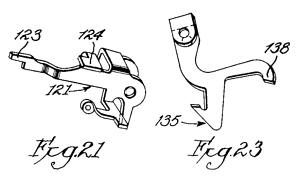
forward. When the bar is pushed rearward in response to a short
keystroke, a latching lever (Fig.21) drops and holds it in position
via the notch at 123. The latch keeps the rest of the keyboard locked
while the trigger is re-armed to complete the short keystroke. When the
trigger is disarmed at the end of the downstroke, it lifts the latch
via tab 124 and thus automatically releases the touch-off bar and the
column locks. When the Mul/Div control is set for Add mode, an
additional master latch (in the leftmost column) holds the touch-off
bar until released manually by the push-button.
- Prepare plain wires 17 and 18 (both 0.088"), 32 (0.0625"), and
33 (0.108"); crimped wire 30 (0.055"); and tie rod G with
plain spacers.
- Prepare the trigger assembly, trigger retainers H and V, and the
touch-off bar latching lever (Fig.21) for the leftmost key column.
- Grasp the latching lever with pliers or tweezers and hold it in
its approximate position near the centre of the column. The lever
pivots on wire 33, with the long arm facing rearwards. Push the loop
of its spring fully on to the plain pin on the frame plate to its
left. Insert the pivot wire 33 (ie, the lock lever stop wire, 0.108")
from the left.
- Place the trigger assembly in position. The pinned end with the
spring faces forward. The rear end initially passes above the
latching lever and the long connecting link passes below. Ensure that
the rear end of the link lies between the segment lever bell crank and
the frame to its left, and is not caught in any of the cut-outs in the
frame plates. Insert the trigger hanger pivot wire 18 (0.088")
from the left.
- Ease the rear arm of the trigger to the left and tuck it under the
tab 124 on the left of the touch-off bar latching lever.
- Start wire 32 (0.0625") from the left. Place the trigger retainer
vertical (TRetV, Fig.23) against the left-hand frame plate, with the
curved end 138 forward between the trigger and the latch, and resting
on top of wire 33. The hooked end 135 must be in front of the
corresponding tab on the rear trigger arm. Feed in pivot wire 32
until flush.
- Fit the trigger retainer horizontal to the right of TRetV. The arms
face forward, with the right-hand offset arm passing throught the
cutout and to the right of the frame. The left arm sits above the
vertical arm of the trigger. Feed in pivot wire 32 to retain.
- Repeat for the remaining columns, then insert the trigger
stop wire 17 (0.088").
- Connect the springs from TRetV to the tabs on the frame plates.
- From the rear, insert wire 30 (0.055", crimped at right-hand side)
and attach the springs from TRetH.
- From the rear, attach the trigger connecting links to the pins on
the segment lever bell cranks and connect the springs.
- Brakes and springs.
- From the front, install the brake levers onto wire 29 (0.108").
The long arm goes on the right, between the keystop levers and the
segment lock lever, and rests against the rear of the large roller
on the segment lever. Make sure that the arm is not caught behind
the small roller on the lock lever. The short arm passes to the left
of the trigger connecting link and helps to hold it onto the bell
crank. Keep the brake lever springs to the top and facing rearwards
over tie rod C.
- Start wires 23 and 24 (0.088") from the left-hand side. The shorter
front wire 23 has a groove at the left which engages with a spring clip
on the second frame plate. (This arrangement was used on earlier
models to provide clearance for the bell, and has been carried over
even though the bell has been deleted). Attach the brake springs to
wire 23, and hang the segment lever springs from both wires to align
with the hooks below. Stand the machine on its left-hand side and
connect the springs to the segment lever hooks. Ensure that any
different springs are returned to their original locations.
- Initial trigger checking.
- Check that the segment lever is held fully upwards against wire 33.
(If not, the key stop levers are probably too far to the left and
caught under the pin on the frame plate). The top of the gear segment
should be about level with the bottom of the hole for tie rod B. Check
that the key tabs on the lock lever stand higher than those on the
segment lever.
- Temporarily install tie rod B and the eccentric adjusting spacers.
Set the spacers carefully to the half-way position, with the high
points all horizontal and facing forward.
- Check that the lower rear tabs of all the triggers are behind the
hooks on TRetV and are not caught above. Check that the crossways
horizontal arms on the triggers are resting on the top of the segment
lever. Check that the left-hand arms of TRetH are sitting above the
vertical arms of the triggers and are not caught behind. Check that the
small horizontal tab at the front of the right-hand arm of TRetH is
resting on the vertical projection on the segment lever and not
jammed beside.
- Check that the pins at the front of the triggers are all in a
straight line horizontally and vertically. The tops of the pins
should be about level with the top of the adjacent frame plate. If any
are out of line, check first that the eccentric spacer is still set
correctly. If necessary, adjust the rest position of the trigger by
carefully bending the horizontal arm which rests on the segment lever
with a suitable tool.
- Take a 4 key (or any suitable flat-ended tool) and press down on
any pair of key tabs near the front of the segment and lock levers.
Check that the front of the trigger moves forward as the lock lever
descends, then lifts upwards until it meets stop wire 17 as the
segment lever starts to move.
- Press down again, and watch the engagement of the left arm of
TRetH with the vertical arm of the trigger. The vertical arm starts
out under the tip of TRetH, then moves forward and clear. Then
simultaneously the vertical arm rotates rearwards and TRetH starts to
descend. The tip of TRetH must end up sitting exactly on top of the
vertical arm of the trigger, with no chance of getting caught behind
during the simultaneous movement. This is the "armed" position.
- Press down again to bring the trigger to the armed position. Hold
this position, then press down slowly on the pin at the front of the
trigger. Watch, listen, and feel for two distinct clicks as the two
trigger retainers drop into position. (This simulates the keystop
disarming the trigger at the bottom of the keystroke).
- Check again that the "feel" and movement of the triggers are
identical in each column.
- When all is correct, insert tie rod G and carefully fit the plain
spacers. Fit the thin spacer and the screw at the left-hand end.
- Remove tie rod B and the eccentric spacers.
- Touch-off bar and column locks.
- Prepare the touch-off bar support assembly 20 and the column
locking hooks. Check that the cross-arms on the locking hooks are not
bent or damaged, and the tiny spring-loaded arms are free to move.
(Excessive force on locked keys will generally bend the cross-arms
before it breaks the segment lever).
- Push the TRetH&V pivot wire 32 to the right until clear of the
leftmost column.
- Feed the touch-off bar support assembly 20 into the large cutouts
near the top centre of the frame plates, with the spring clips on the
left-hand side and the arms facing forward. When fully inserted,
rotate the arms down into the gaps behind TRetV, keeping them in front
of the spring anchor wire 30. Spread the outer frame plates slightly
and engage the pins on the end of the bar with their bearings. Check
that the bar swings freely.
- Push wire 32 back home, through the hole in the left-hand arm of
the support assembly, so as to limit the movement. Attach the spring
3x7x0.2 from the left-hand arm to the tab on the frame.
- Hold the leftmost locking hook with the movable arm at the top
left. Press the segment lever down and hold. Lower the locking hook
down into the column, pass the right-hand arm through the frame cutout,
back up, and hook the tab over the frame plate. Release the segment
lever and insert pivot wire 22 (0.088"). Check that the cross-arm
of the locking hook is behind the fixed hook on the segment lever.
Continue to the end.
- Insert the touch-off bar 31 (1/16" square) and the column lock
retainer 21 (0.088", grooved) into the touch-off bar support arms
from the left-hand side. Engage the spring clips with the grooves
in the wires.
- Push the touch-off bar rearward and check that the locking
hooks swing freely into position under the corresponding hooks on
the segment levers. Release the touch-off bar and check that all the
hooks move clear of the segment levers.
- Key stops.
- Check the loops on the free ends of the long keystop springs and
re-form if necessary so that they are just slightly open. Check the
half-round pins on the bottom ends of the keystops and ensure that
they are still firmly riveted to the arms.
- Start at the leftmost key column. Fit the smaller keystop into the
column with its short right-hand arm over the top of the frame plate.
Engage the right-hand tab on the horizontal arm with the hook on the
key stop lever. The left-hand tab sits above the trigger.
- Turn the larger keystop 90° to the left. Place it over the
first, engage the hook, and feed in wire 13 (0.108") to retain. Check
that the tabs are still properly engaged. Check that the keystops are
free to move and are not jammed against the segment lever.
- Repeat for the remaining columns. Remove the support plate to
install the upper keystop in the right-hand column. Do not replace the
support plate yet.
- Prop up the machine on its back and connect the keystop springs to
the tabs on the frame plates. Use a long wire hook to pull the loop
of the spring up against the tab, and a wider tool to push or pull the
body of the spring into a position where the loop can be slipped into
the hole. Ensure that the loop is fully engaged. Although it looks
impossible at first, the springs can all be connected up in about 10
minutes after a bit of practice.
- Set the machine on its feet. Insert a 4 key in the first column,
between the lock lever and the key stop levers and just forward of
the trigger hanger, and engage it with the fourth set of key tabs
on the long levers. Press the key fully down and check for smooth
operation of the even key stop. Move the key to the third set of tabs
and check the odd stop. Correct as necessary, then repeat for
each column.
- Accumulator interlocks.
- Remove tie rod B and the eccentric spacers.
- Prepare the subtraction cutoff lever, the accumulator latch, the
accumulator locking hook (ALH) and the pinion ratchet reverse lock
(PRRL) for the leftmost key column, and two plain wires 0.088" and
0.0625". If the parts have not been kept in column order it will be
necessary to sort the sub cutoff levers into their original colour
groupings. Attempts to rearrange the coloured buttons later will
result in breakages.
- Hold the subtraction cutoff lever above the active column. Pass
its lower end through the top front cutout in the frame plate to its
left. Move it down and across to the left into the outer (keyless)
column, and engage its right-hand side with the small locating tab on
the right of the frame plate. Insert wire 11 (0.088") to retain.
- Place the accumulator latch onto the end of wire 11, at the left
of the active column. The vertical end passes under the keystop
wire 13 and points upwards at the rear. Push wire 11 in until flush
with the end of the latch. Push wire 12 (0.0625") through the notch
in the subtraction cutoff lever and attach the latch spring
2.8x4x0.18 to wire 12.
- Engage the fork on the rear of the accumulator locking hook with
the pin on the front of the trigger, then lower the ALH down into
position. Push wire 12 into the left-hand arm only, and insert a
spare wire from the right to support the opposite arm.
- Check that the small spring 2.8x3.6x0.22 is securely attached
between the two holes in the central tab of the pinion ratchet reverse
lock. Place the PRRL between the arms of the ALH, with its long arm
downwards on the right. Feed in wire 12 to retain. Draw the spring
forward and attach it to the bridge of the accumulator locking hook.
- Repeat for the remaining columns.
- Accumulators and carry levers.
- Replace tie rod B and the eccentric spacers. Re-set the cams to
the half-way position with their high points facing forward. Check
that all the segment levers are resting against the underside of the
spacers.
- Check all accumulator parts for dirt or damage, and ensure that
the ratchet pawls move freely.
- Assemble the accumulator for the leftmost (overflow) column. This
accumulator has a plain spacer at the right instead of the pinion
ratchet. Place it into position and feed in pivot wire 5 (0.088")
to retain.
- Assemble the accumulator for the next column. Hold the assembly
in tweezers so that the deep cut on the pinion is one tooth forward of
the top. Press down on the rear of the accumulator latch to provide
clearance, then ease the accumulator up into position. Engage the
pinion with the segment rack and feed in the pivot wire. Check the
deep tooth alignment and correct if necessary.
- Continue to the end. Check again that all the segment levers are
fully up and all the deep teeth on the pinions are correctly aligned,
one tooth forward of top.
- Prepare the backstop, backstop spring, carry lever, and latch
lifter for the rightmost column. Check the carry lever very carefully.
Ensure that the roller pivot is still firmly riveted and that the
roller turns freely. Remove any burrs on the three rearward-facing
points so that they can not catch on the lantern wheel. Check that the
three riveted levers all move freely, and that the spring(s) are not
damaged or distorted.
- Start the backstop wire 6 (0.088") from the right-hand side. Place
the backstop in position over the lantern wheel and feed the wire into
the right-hand arm only. Feed in a follow-through wire from the
opposite side to support the left arm.
- Hold the backstop spring with the hooked end upwards at the right
and place the coils between the two arms. Advance wire 6 through the
coils. Note that backstop in the rightmost column has a stronger spring.
- Place the carry lever assembly in position beside the backstop
and support it with the two wires.
- Place the latch lifter between the arms of the carry lever, with
the cut-away section of the hub at the top left. Ensure that the longer
rearward arm sits under the tab on the accumulator latch lever. Advance
wire 6 to the next column and continue to the end.
- Support the front of the machine a few inches off the bench. Press
the top of the backstop spring back and down with a finger, catch the
end from underneath with a fine spring hook, and sit the end of the
spring on the edge of the frame plate. Remove your hook, then push the
end of the spring to the right so that it hooks over the frame. (If you
put the spring in position directly you will have trouble removing
your hook). Ensure that the spring is securely hooked over the frame,
then continue to the end.
- Fit the top front tie rod E and the special formed spacers with the
rolled lip pointing upwards at the front. Ensure that the top arm of
the carry lever is below the rear of the spacer and not caught above.
- Insert the spring retainer wire 8 (0.0625") and attach the
carry lever springs. The springs must come off the top of the tab on
the carry lever, not from the bottom or side. The top loops should be
on the left so that the springs do not rub on the upper arm of the
lever. Lift the spacers hard up against the wire.
- Lift the bottom rear pawl of the carry lever and push it rearward,
so that it passes above the segment lever roller and engages with the
lantern wheel. (Lift the ALH if necessary). Temporarily insert the
intermediate gear shaft 7, which acts as a forward stop for the carry
levers when the segment lever is lowered. Check the the fine torsion
springs on the carry lever are still in position.
- Accumulator and trigger checking.
- While carrying out some of these checks it is necessary to keep the
accumulator latch clear of the accumulator gear. Lift the front of the
latch with a small hook, or press down on the rear end without touching
the trigger. When fully assembled, the latch will be raised
automatically by the latch lifter whenever the rock frame is engaged.
Perform these checks and adjustments carefully, as most of the
mechanism will be inaccessible once the keyplate is installed.
- Insert a No. 3 key in the leftmost column, between the key stop
levers and the lock lever, with the right-hand shoulder above the
third operating tab on the lock lever. Lift the accumulator latch and
slowly press the key fully down. Watch and listen for the trigger
retainer operation as before. Let the key rise very slowly, and check
that the backstop drops over the third lantern wheel bar just as the
segment lever reaches the top of its stroke. Adjust the eccentric
spacer so that the backstop engages reliably every time, with minimum
over-run of the lantern wheel. Check several times to engage with
different bars on the lantern wheel. If larger or unobtainable
adjustments are needed, it is likely that the pinion deep tooth
alignment is incorrect, or the pinions, lantern wheels, and backstops
have been mixed and are no longer paired correctly.
- Make a full keystroke (down and back). Release the accumulator
latch, and check that its forward arm drops fully between the teeth of
the accumulator gear. The gear should not move as the latch engages.
Adjust the eccentric slightly if necessary, then re-check the
backstop operation.
- Partially depress the key so that the pinion ratchet only advances
2 clicks, then let the key rise slowly. Check that the trigger operates
the column locking bar as the lock lever rises. You should hear another
click as the touch-off bar latching lever drops into place. Press down
slowly to complete the keystroke, and check that the column locking bar
resets as the keystop presses down on the trigger, just before the
key reaches the bottom. Check again that the trigger retainers H and V
drop into position at the bottom of the keystroke, with sufficient
excess movement to ensure reliable operation.
- Lift the accumulator latch and push the carry lever rearwards.
Check that it advances the accumulator by one place, and that it
returns fully when released slowly. Repeat 10 times to check every
bar on the lantern wheel. If the lever stops half-way, check for
tight pivots, damaged or mis-placed springs, burred pawls on the
carry lever, or damaged bars on the lantern wheel. If these are all
correct, increase the clearance for the overrun pawl by setting the
segment lever eccentric stop a little lower, then re-check that the
backstop and accumulator latch still operate correctly. There is a
fairly limited range in which all these adjustments will be correct.
- Repeat for the remaining columns. When all columns are working
correctly, tighten the screw at the left of tie rod B to lock the
eccentrics in position.
- Mul/Div control.
- Push tie rod G and wires 17, 18, and 33 to the right until clear
of the leftmost column.
- Fit the touch-off bar master latching lever to wire 33, making
sure that its long rearwards arm is above the touch-off bar 31. The
lever is similar to the the column latching levers in Fig.21 above.
- Put the release plate 14 in position above the keystops, with its
fingers facing upwards from the rear of the shaft. Engage the pinned
ends with the bearings in the outer suport plates, then attach the
spring 3.5x7x0.3 to the keystop wire 13.
- Insert a plain frame spacer into the hub of the Mul/Div lever
assembly and place it in position on tie rod G. Engage the forked arm
into the groove near the left-hand end of the release plate. Push the
release plate rearwards to horizontal and check that pressing further
pulls the Mul/Div lever forward (via the pin next to the forked arm).
Fit the narrow spacer and screw at the left of tie rod G.
- Hold the latch release lever with the straight arm vertical on the
right. Lower the curved arm down into the column and start the trigger
hanger wire 18 into the right-hand side. Attach the spring 3x15x0.2
from the latching lever to wire 18, then feed the wire right through.
Rotate the release lever so that the long curved arm comes up under
the rear of the latch lever, then tuck the forward arm under the tab
on the left-hand end of the release plate 14. Attach the spring
3x15x0.3 from the latch release lever to wire 19 (0.088", crimped on
left, short on later models).
- Attach the spring 3x16x0.4 from the bottom of the Mul/Div lever to
the trigger stop wire 17.
- Fit the error release button shaft 15 to the slots in the top of
the frame plates. Early models have a clip to a frame plate secured by
the second crimped wire 16, and a tension spring 3x28x0.2 to the
keystop wire 13. Later models have two circlips around the shaft 15
and a torsion spring around wire 16.
- Press the Mul/Div lever down and rearwards and check that it
latches under wire 16, then pull it forward to disengage. Push the
touch-off bar 31 rearward and check that the master latch operates to
hold it in position. Press the error release button and check that
the latch releases. Engage the latch again, press down on the release
plate 14 to simulate clearing the machine, and check that the latch
releases.
- Engage the Mul/Div lever. Push the touch-off bar rearward and
check that it does not latch. Press down on the release plate and
check that the Mul/Div lever disengages. (A field service modification
was available so that the Mul/Div lever would remain engaged until
released manually. This involved removing the pin at the left of the
release plate so that the forked arm would not be drawn forward when
the machine was cleared).
- Cross-shafts and right-hand side.
- Fit the short tie rod I with plain round spacers. Fit washers over
the tie rod at each end and firm up the screws.
- Be careful not to over-tighten any of the small tie rods. These
rods are only 5/32" aluminium with a coarse 7/64" internal thread.
There is only 0.023" of metal on each side, which can easily be pulled
apart by over-enthusiastic tightening. A machinist can repair or
replace a broken rod, or a home-made replacement can be cut from
5/32" steel with external threads, nuts, and washers at each end.
Make sure that the replacement rod does not interfere with the
mechanism retainer plates.
- Flip the machine over (front to back), with a suitable support to
keep the subtraction buttons off the bench. Fit tie rods J and K (with
two internal threads) and plain spacers. Replace the two internal feet
and the short spacers in the original columns. Look for the oil stains
on the frame plates to locate the feet, or match the feet with the
impressions in the lining of the base.
- Start tie rod H and fit the formed spacers. The open side of
the spacers faces the baseplate, with the single folded tab pointing
forward. These spacers must be aligned correctly to avoid blocking
the movement of the No. 6 keypieces.
- Stand the machine on its left-hand side and remove the right-hand
support plate. Check that the bearings for the release plate 14 and the
rock frame actuating shaft 2 are still firmly riveted to the plate.
These bearings take a considerable load as the machine is cleared, and
sometimes become quite loose. Repair as necessary.
- Assemble the clearing handle mechanism on the support plate. Adjust
the inner sleeve to provide free movement with minimal side play.
- Place the detaining toggle release bar support 27 in its bearing
in the left-hand suport plate, with the clip at the left-hand side and
the arms facing outwards. Then rotate the bar so that the arms face
straight up into the mechanism.
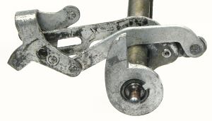 Arrange the links on the rock frame actuating shaft 2 so that the
triangular bell crank for the shutter reset mechanism sits above the
longer slotted link, as shown opposite. Place the shaft assembly in
its bearing in the support plate, with the links above the shaft and
facing forward. Ensure that the leftmost links are above the front
foot.
Arrange the links on the rock frame actuating shaft 2 so that the
triangular bell crank for the shutter reset mechanism sits above the
longer slotted link, as shown opposite. Place the shaft assembly in
its bearing in the support plate, with the links above the shaft and
facing forward. Ensure that the leftmost links are above the front
foot.
- Place the spacers on all the tie rod ends, matching the heights to
the tie rod nuts and the offsets in the support plate. Later models
have a flat plate with all nuts and spacers 0.25". The spacer with the
reduced outside diameter goes on tie rod H. Fit the interlock L-lever
over this spacer, with the connecting link towards the rear.
- Fit the support plate over the tie rod ends. Check that the outer
rock frame links are above the front foot. Engage the rock frame
actuator shaft, release plate, and detaining toggle release bar with
their bearings and their clearing mechanisms. Check that the support
plate sits flat across the spacers. Fit the large screws and washers
to tie rods A,B,C, making sure that the washers are centred over the
rods. Firm up the screws in rods A,B,C from both sides, then check
that the rock frame actuator and the detaining toggle release bar
still have a small amount of end play.
- Place the machine back on its feet, with a block under the front to
protect the rock frame links. Check that the release bar has a (very)
small amount of end play. Check that the reset arm at the right of the
release plate is aligned with the clearing arm below, and has no chance
of slipping off. Check that the release plate fingers are properly
aligned with the rear ends of the accumulator locking hooks. It may be
necessary to loosen the right-hand side, lift the release plate, and
adjust the hooks and/or triggers sideways to ensure positive engagement.
- When these adjustments are correct, fit the remainder of the screws
and tighten from both sides. Make a full and a short keystroke in
every column (as described under "Trigger and accumulator checking"
above) to check that tightening the frame has not caused anything to
bind or stick.
- Rock frame detaining toggle.
- Stand the machine on its back, with a suitable support to stop it
falling backwards. Assemble the two parts of the detaining toggle and
place in approximate position behind tie rod F in the leftmost column,
with the long link rearwards and above the central tie rod H. Spread
the frame plates and ease the short shaft into the bearing holes 1.
- Place the long link from the detaining toggle between the two tabs
on the left arm of the release bar assembly 27. Insert the plain end of
the release bar 28 (0.088", grooved) to hold the link in place. Push
wire 28 through to the right-hand side and engage the link from the
clearing mechanism. Check that wire 28 is behind the tails of the brake
levers and properly engaged with the clip on the left-hand side.
- Place the short forward link from the detaining toggle onto the
grooved pin on the operating arm near the left of the rock frame
actuating shaft.
- Connect the spring 4x40x0.4 from the detaining toggle to the tab
on the leftmost frame plate.
- Connect the larger spring with the slotted link to the post at the
top centre of the leftmost frame plate. Pull the link forward with a
spring hook and fit the slot onto the grooved pin at the left of the
rock frame actuating shaft, so as to retain the link from the detaining
toggle.
- Fit tie rod F and plain spacers. The leftmost spacer has the
diameter of its centre section reduced from 0.025" to 0.020" to provide
an over-centre stop for the detaining toggle. Fit the rock frame
actuating shaft support plate and short spacer near the centre of
the tie rod - look for the oil stain on the frame plates.
- Place the machine back on its feet, with a block under the front to
protect the rock frame links. Carefully pull the clearing handle
forward, making sure that the rock frame links do not catch on the
frame or the carry levers. Check that the handle moves and returns
freely. Insert a key in any column and check that the detaining
toggle releases.
- Rock frame assembly.
- Check the carry lever locking dogs (rivetted to the rock frame
plates) and ensure that they move freely.
- Assemble the tie rods, frame plates, and spacers according to your
map. Fit the screws but do not tighten yet.
- Place the rear (wide) side flat on the bench with the curved end
plate to the left. Fit the pairs of escapement levers with their short
arms under the clip at the left-hand side. Note that there is a
special pair for the leftmost (overflow) column.
- Fit the toggle lever and zero stop assemblies. There is a narrow
lever at the left, one with a spring clip at the right, and levers
with actuating forks in alternate columns between. If the toggle
levers and zero stops have become separated they are best assembled
on the end of a spare wire held in a vice, as the torsion springs
are quite strong.
- Turn the frame over and insert the locking dog stop wire.
- Close the retainer plates at each end and insert the intermediate
gear shaft 7 (0.108") through the top holes. Hold the frame against
a flat surface and tighten the screws from both ends. Be careful not
to over-tighten. Remove wire 7 and open the retainers. Be careful not
to twist the rock frame during further operations.
- Check that the roller at the front of the carry gear cam turns
freely, then assemble the carry gear, spring, and escapement. Wind
the spring to restore the pre-load found on disassembly, then hook the
escapement arm behind the stop pin on the gear. Fit the assembly into
the frame and insert the pivot wire. It will help keep the parts
together if you assemble them on a short temporary axle (about 5/8" of
1/16" rod) which can be pushed out as you insert the pivot wire.
- Hold the zero stop clear of the carry gear stop pins, rotate the
gear by hand, and check that the escapement wheel follows half a turn
at a time. Close the retainer plates.
- Shutter reset links.
- Support the front of the machine on a suitable block. Push
rearwards on the detaining toggle release bar 28 to release the
toggle. Check that the outer rock frame actuating links are resting
on the front feet and the inner links are hanging below the frame.
- Take the leftmost shutter reset link (the one with the tiny spring
clip) and hold the link vertically, with the curves forward and the
bottom tab offset towards the left. Insert the straight end into the
leftmost (overflow) column, between the left-hand frame plate and the
accumulator gear and behind the accumulator shaft. Fit the remaining
links in alternate columns to align with the rock frame actuating
links below. Ease the links down between the subtraction cutoff lever
and the accumulator latch so that they sit on the accumulator shaft
at the same level as the first. Check that the lower ends of the links
are on the right of the frame plates and not caught in the cutouts.
- Starting from the right-hand side, fit the curved shutter links to
the left of the vertical links, with the tab curled over the top and
the free end facing forward. Insert wire 10 (0.075", narrow groove at
left) from the right-hand side to retain. Engage the clip at the left
with the rear of the groove.
- Rock frame installation.
- Check again that the intermediate gear shaft 7 (0.108") passes
freely through the holes in the top of the rock frame and the
corresponding holes in the main frame plates. Correct any tight spots
by feeding a 7/64" drill bit in from the end and easing the hole on
the side flutes of the drill.
- Check that the formed spacers on tie rod E are hard up against the
carry spring wire 8. Loosen the tie rod and correct as necessary.
- Support the front of the machine about 100mm (4") off the bench.
Push rearwards on wire 28 to release the detaining toggle. Press
rearwards on the front arms of all the accumulator latch lifters so
that the rear arms stick in position up under the latches.

- Cut a piece of 1/16" rod or wire to slightly less than the width
of the rock frame. This will be used as a temporary locking wire to
keep the mechanism at zero during installation.
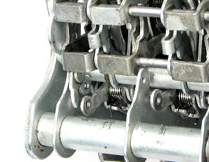
- Stand the rock frame on the bench with the forked levers at the top
and the carry gears behind. Push the forked end of the right-hand
toggle lever rearward against the tie rod, then draw the carry gear
upwards until the spring is under tension. Lift the toggle lever
so as to engage the zero stop, then insert the temporary wire through
the hole in the toggle lever as shown in the illustration opposite.
Continue to the end.
- Check that all the zero stops are standing about half-way under
the stop pins on the carry gear. Serious misalignment can be corrected
by carefully bending the small spring-loaded tabs between the zero
stop and the toggle lever.
- Do a final check that all the carry gears are still under tension,
the carry levers are still engaged with the accumulators, the fine
torsion springs on the carry levers are still in position, and the
latch lifters are still rearwards.
- Hold the rock frame at each end and carefully insert the lower
arms under the carry levers. Rotate the bottom rearwards until the
leftmost escapement lever sits over the toggle link attachment point,
as shown for removal. Let the rock frame sit in this position while
you place the intermediate gears into the gap at the right of the
carry gears. The recessed side of the gear faces to the left. (It is
not strictly necessary to put the intermediate gears in position at
this stage, as they can be installed later from the top. However,
when it becomes necessary to remove and replace the rock frame for
maintenance the top access will be blocked by the numeral wheels.
This slightly more complex procedure can be used in both cases).
- When the rock frame is sitting correctly, the top will swing easily
under the spacers on tie rod E. Difficulties may be caused by
incorrect assembly of the tie rod end fittings, the lower arms
fouling on the actuating links, the toggle links fouling on the
attachment rivets, the carry gear fouling on the forward arm of the
carry lever, or the temporary locking wire being too long.
- When the rock frame passes under the tie rod, rotate it inwards
and upwards and move it further left to engage the lateral locating
flanges on the top tie rod with the frame plates. Insert pivot wire
7 (0.108") to support the rock frame, or use temporary 7/64" pins
from each side.
- Check that the rock frame swings freely back and forth on the
pivots. Push the rock frame rearwards and check that all the
accumulator latches lift slightly. If any fail to move, remove the
pivots, draw the rock frame forward, and push the latch lifter down
behind its operating pin. Replace the pivot wires and check again.
- Pull the rock frame forward and connect all the toggle links and
levers to wire 4 (0.075", with a ring at right-hand side). Remove the
temporary locking wire.
- Remove the temporary pin, stand the machine on its left-hand side,
and connect up the rock frame actuating links. Starting at the top,
engage the shutter reset link with the pin at the rear of the
triangular bell crank. Engage the pin on the slotted actuating link
with the fork on the rock frame toggle lever. Align the hole in the
bell crank with the slot in the link and feed the supporting wire 3
(0.088") through both. Rotate the actuating shaft slightly to align
the holes. It gets easier after the first couple are in place. The
wire should pass easily through all the links without forcing.
- Attach the two helper springs from the toggle wire 4 to the formed
spacers on tie rod A. Loosen the tie rod and adjust the spacers so
that there is a slight tension on the helper springs.
- Rock frame toggle testing.
- Place the machine back on its feet and replace the temporary pivot
pin. Carefully operate the clearing handle, freeing the shutter links
if they become caught. Check that the rock frame moves forward and
that the detaining toggle locks over-centre. Check that the clearing
handle still returns freely.
- Push rearwards on wire 28. Check that the detaining toggle releases,
the rock frame snaps down and rearwards, and the shutter reset wire
rises evenly about 5mm. Free the curved links if they become caught.
The rock frame movement must be quick and positive.
- Look in from the left-hand side and check that the large carry gear
is fully engaged with its accumulator gear.
- Clear and release the rock frame again. Examine the small toggle
links 4 closely to ensure that they are all fully over-centre. If
either end of pivot wire 4 can be pushed down further it usually means
that the rock frame is twisted. Correct as necessary so that the rock
frame toggles all engage quickly and fully when the detaining toggle
is released.
- If the rock frame does not engage fully, the problem may be in
the actuating links or in the engagement of the gears. The zero
position of the carry gear depends on the zero stop levers and the
zero studs, which may be loose or damaged. The zero position of the
accumulator gear depends on the eccentric spacer setting and the
alignment of the pinion deep tooth. Mis-alignment can cause a pair of
gears to clash tip-to-tip and prevent the rock frame from engaging
properly. Locate and correct any errors before proceeding.
- Readjust the helper springs so that they are still under a slight
tension when the rock frame is fully engaged.
- Numeral wheels and shutters.
- If the machine has coloured numeral wheels, arrange them in order
to match the keytops. Note that the wheels are not all the same, due
to the shorter hubs in the columns with the shutter reset links.
- Clear the machine. Starting at the left, place the shutter assembly
inside the numeral wheel and ease it into position from the front. Pass
the long arm (the sub cutoff latch) through the frame and up against
the pin on the sub cutoff lever. Pull the assembly forward and arrange
the short rearward arm in front of the shutter reset wire 10.
- Start the numeral wheel pivot wire 9 (0.0625") from the left and
engage it with the curved shutter link. Align the wheel and shutter
and feed the pivot wire through. Check that the wheel spins
freely - ease the frame plates if necessary.
- Connect the stiff spring from the sub cutoff lever to its latching
lever. Pull the loop forward with a spring hook and twist the end into
the hole with a pair of fine bent-nose pliers or similar. Ensure that
the loop is properly formed and fully engaged.
- Fit the sub cutoff latch release lever flat against the right-hand
side plate, with the lower offset arm to the right of the carry lever
spring. Engage the forked end with the locking dog stop wire in the
rock frame (immediately below the top tie rod), then ease the top end
rearwards past the shutter operating arm. The arm should then drop
freely into position without binding or sticking.
- Install the remainder of the numeral wheels, shutters, and latch
release levers.
- Hold the rock frame in position and swap wire 7 to the left and the
temporary pin to the right. Set the leftmost numeral wheel to zero,
lift the intermediate gear so that it engages with both the numeral
wheel and the carry gear below, and feed in the pivot wire. The hollow
zero should be centred over the silver section of the shutter behind,
and just slightly forward relative to the raised section on the
frame plate.
- Push the intermediate gear to the left, then pull back the pivot
wire to leave a gap between the gear and the frame plate to its right.
- Take the shutter release lever and check that it is not bent or
twisted. Check that the roller turns freely, and that the fine torsion
spring is properly located in its groove. Wind the spring clockwise
so that both ends are in front of the side tab, hold the spring with
your thumb, then insert the left-hand arm and roller into the gap in
front of the intermediate gear hub. Slide the arm downwards and
rearwards into position. When you have to let go of the spring it
should stop on the top tie rod, then finally come to rest in the notch
at the right of the sub cutoff latch release lever. Align the levers
and feed in the pivot shaft from the left. Continue to the end.
- Insert a key (eg 3) in the leftmost column, between the key stop
levers and the lock lever, and above the operating tabs on the lock
lever. Make several full strokes of the key and check that the
mechanism operates as expected. Check that the tens-carry proceeds
into the next column. Make short strokes and check the operation of
the touch-off bar, column locks, and release button. Repeat for the
remaining columns. Check thoroughly, as the trigger and eccentric
spacer adjustments will be inaccessible after the keyplate is fitted.
- Clear the machine and check that all the zero shutters are closed.
Press a key in the rightmost column and check that only the rightmost
shutter opens. Clear and repeat in each column, checking that all
and only the shutters to the right of the column will open. Adjust
the cascaded shutter levers as necessary so that they trip and
reset correctly.
- Clear the machine and use a 9 key to enter 999...999. Press the
rightmost subtraction cutoff button and check that it latches
rearward. Add 1 in the rightmost column. Check that the numeral wheel
advances to 0 without producing a carry, and that the cutoff button
springs forward. Repeat for the remaining columns.
- Press all of the subtraction cutoff buttons rearward so that they
latch in position, then check that they are released when the clearing
handle is operated.
- Keyboard.
- Check the locating tabs under the keyplate, and the places where
they engage with the tops of the frame plates. Any distortion or
misalignment can make it difficult to insert some of the keys and
may cause the columns to jam.
- Engage the front of the keyplate under the tabs at the front of the
frame plates, then lower the back. Look in from the rear to check that
the locating tabs are properly engaged. Check that the plate sits flat
all round. Insert two retainer wires (with right-angled ends) from the
left, through the notches in the top of the leftmost frame plate.
Insert the third retainer at the right-hand rear of Sterling (or
ex-Sterling) machines. Leave the end of the central wire outside the
leftmost frame plate, so that it can not interfere with the touch-off
bar support.
- Prepare the keys in their colour groups and drop them into the
keyplate. The hooks at the bottom of the keys should be flat, but
resist the temptation to straighten the 1 keys. The bends are
deliberate, to provide clearance from the upper keystop.
- Prepare the keypieces and graduated springs. Springs for rows 1
and 2 are 0.028" diameter, 3 and 4 are 0.0265", 5 and 6 are 0.025",
and 7, 8, and 9 are 0.023". Wear eye protection while handling the
springs.
- Support the machine vertically on its back. Start at the bottom
left (as you look at the underside) and check that the 9 keystem passes
between the key-stop levers and the segment lock lever. Engage the
right-hand leg of the keypiece in its slot, fit the hole over the
keystem, then engage the left-hand leg. Place a finger over the coil
of the spring (to stop it flying off), then hook the tail of the
spring under the tab near the left foot. Push the spring fully to the
left on the supporting pin so that the coils can not work loose.
Proceed left to right across the columns, then upwards, one row
at a time.
- With the machine still vertical, press every key and check for any
problems. The keypieces are quite soft and are easily bent out of
shape (and back again). Make full keystrokes and check for keypieces
that rub against their neighbours or adjacent keystems. Make short
keystrokes, moving only the lock lever, and watch carefully for keys
that do not return fully. This problem is usually due to the keypiece
holding the keystem too far to the left, causing the key stem to bind
on the horizontal flange on the frame plate. Straighten the keypiece
or adjust its left foot to correct. Keys and keypieces can be removed
individually - it is not necessary to disassemble the entire
keyboard. Problems can also be caused by incorrect fitting of the
keyplate so that the locating tabs distort the frame plates and cause
the keys to bind. When all seems correct, place the machine back on
its feet and check again.
- Check the adding, carry, and duplex operation by adding all the
numbers on the keyboard, 3 at a time. Start with the leftmost three 9s,
then the 8s, and so on down the column, then the next three columns,
etc. The result should be 499...995. Add 1 five times and check that
the ripple carry proceeds quickly and smoothly across the whole
register. Test extensively before refitting the casing.
- Casing.
- Cut new rubbers (if necessary) for the locating lugs on the
baseplate, and fit a new tranparent window to the top cover. Repair
any bent or damaged decimal indicators.
- Invert the machine and set it down on a soft cloth. Fit the
baseplate with 4 screws through the rubber feet. Set the machine
down on the base.
- Fit the mechanism wire retainer plates with 3 screws each side.
- Fit the top cover, lay the machine on its side, and fit the
small screws around the edge of the base. Note that there is
very little clearance between the top cover and the back of the
segment levers, to the extent that any damage to the cover or to the
sound deadening material can cause the segment levers to bind. Check
the operation of each column after fitting the cover, then fit the
control buttons.
Problems in assembly.
Many of the potential problems have been addressed in the
relevant sections of the notes, but there are plenty more things
that can go wrong. Problems are much more likely if the parts have
not been kept in column order. Here are a few of the more subtle
problems that may result from errors or oversights in assembly:
- A column usually works but sometimes blocks, especially if operated
slowly. This is usually due to friction or interference preventing a
key from rising fully. The key must rise right to the top of its travel
in order to reset the trigger and release the pinion ratchet
reverse lock. Likely causes are:
- keypieces rubbing together, or holding the key too far to the left
- a mis-aligned spacer on tie rod H preventing the No 6 keypiece
from rising fully
- keystems not passing freely between the keystop and lock levers
- incorrect engagement of the keyplate locating lugs, causing
distortion of the frame and binding of the keystems.
- A column was working, but is now blocked. This may be due to a
spacer on tie rod E being knocked out of position while handling the
machine, so that the rear edge of the spacer fouls against the
intermediate gear. It can also be due to the latch lifter not being
properly engaged with the operating pin on the rock frame, so that
the intermediate gear catches on the edge of the cut-away section
of the latch lifter hub.
- A column has keys 2 to 9 blocked, but the 1 key operates correctly.
This is caused by the rear of the 1 keystem pressing against front edge
of the upper keystop and holding it engaged with the segment lever.
The segment lever can only move down as far as the first stop, which
is sufficient for the 1 key but not for any of the others. Remove the
1 key and carefully increase the curvature - concave side towards
the rear.
- A column passes from 9 to 0, the carry lever makes a full stroke,
but the carry does not happen. The subtraction cutoff lever may be
stuck and in contact with the underside of the carry lever pawl, or
the pawl spring may have been displaced during rock frame
installation.
- A column passes from 9 to 0, the carry lever is released, but is
unable to complete its rearward stroke. This is usually due to excessive
friction, or incorrect balance of spring tensions. Check that all the
register compnents have a small amount of sideways movement and are not
jammed between the frame plates. Check that the carry lever spring is
attached to the top of the lug on the carry lever and not twisted from
the side or back. If these are correct, it is likely that incorrect
carry springs or preloads have been installed in either the carrying
or receiving columns, or that the carrying spring is fatigued. These
problems are more likely in non-decimal columns.
- A variant of the above is when the column carries correctly if the
receiving column is at zero, but fails with high numbers. This
indicates that the carry spring is able to overcome friction and the
preload of the receiving column, but has not stored sufficient energy
to overcome the increased spring tension as the count advances.
Increasing the pre-load may help, but may create the same problem
for the column on the right. Incorrect springs and pre-loads can also
lead to a situation where the force of the segment lever springs,
divided by the lever and gear ratios, is insufficient to wind the
carry spring as the count increases.
- Many intermittent errors can occur if the carry lever does not
return promptly, or does not latch correctly under its locking dog at
the end of its return stroke. When the column is operated the overrun
detent may pull the carry lever rearward, causing an erroneous carry
into the next column. Check first that the locking dog is free to move,
and that the carry lever spring has not been stretched or damaged. If
these are correct, the problem may be due to the segment lever zero
position being set too high. Insufficient clearance between the lantern
wheel and the segment lever roller results in the carry lever spring
having to overcome the overrun pawl torsion spring as it attempts to
pull the carry lever forward. Adjust the eccentric stop to lower the
segment lever slightly, then re-check the backstop and accumulator
latch.
- The previous problem is more difficult if it occurs in the
leftmost (overflow) column, as there is no segment lever to adjust.
(The pawl slides over a fixed pin attached to the frame plate).
Remove the rock frame and polish the sliding surfaces, or ease the
top of the pin slightly to provide clearance.
Ongoing maintenance
- The best way to keep a Comptometer in good working order is to
exercise it regularly, and to re-lubricate whenever it shows signs
of slow or sticky operation.
- Exercise the machine by adding all of the numbers on the keyboard,
3 at a time. Start with the leftmost three 9s, then the 8s, and so on
down the column, then the next three columns, etc. The result should
be 499...995. Add 1 five times and check that the ripple carry proceeds
quickly and smoothly across the whole register.
- Lubricating the cross-shafts of a Comptometer is done with a set
of follow-through wires of 0.0625", 0.088", and 0.108" diameter. Clean
the 1/16" wire, apply a drop of oil to the front, and use it to push
the numeral wheel pivot wire 9 out of the machine. Clean the original
wire (with fine emery cloth if necessary), apply a drop of oil, and
push it back from the opposite direction. Repeat as necessary until
the wire comes out clean.
- Repeat the same process with wires 5, 6, and 7.
- To clean and lubricate the carry gear pivot wire in the rock
frame, the intermediate gear wire 7 must be replaced with a
temporary follow-through wire. The temporary wire must be shorter
than the rock frame, so that the two hinged retainer plates at the
ends can be opened at the same time. Then follow the same procedure.
- Wires whose parts have more limited movement can be withdrawn less
frequently, or lubricated directly with a small artist's brush. Do not
withdraw any wires (eg 13) that are also used as spring anchors.
- Invert the machine and apply a small drop of oil to the side of
each lantern wheel, so that it runs in and lubricates the pinion
ratchet.
- Use a small artists brush to apply a minimum amount of oil to the
other moving parts, pivots, and bearings, including the carry lever
locking dogs and the rock frame toggle links.
- Exercise the machine again to distribute the oil before replacing
the covers.
Original text and images Copyright © John Wolff 2004-2022.
Last Updated: 18 March 2022.
Back to: Home
Calculating Machines
Key-driven calculators
Comptometer
Model J
Tech Index
