Contents
Contents |
|
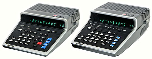
| Sharp PC-1001 (1973) and PC-1002 (1974). |
The Sharp PC-1001 and PC-1002 are pair of compact scientific desk calculators from the early 1970s. Both are mains-powered machines with a "10+2" scientific display, 8 memory registers, and the ability to store programs entered from the keyboard. Scientific functions include powers, logs, and trig functions which are generally accurate to 9 figures.
Both machines have essentially the same internal circuitry, which is built around a general-purpose 4-bit microprocessor system (the Rockwell PPS-4) rather than a dedicated calculator chipset. The functionality of each machine is defined by the programs stored in its Read-Only Memories. The PC-1001 has two ROMs containing the basic and scientific functions; the PC-1002 has a third ROM with angle and coordinate conversions and basic statistics.
The PC-1002 was one of the first calculators to offer optional pre-programmed ROM modules which could be installed by the user (or the Sharp agent) to extend the capabilities of the machine. Chips were produced for statistics, mathematics, metric conversion, and surveying. Further chips were planned for electrical and structural engineering, finance, and other fields, but it is not known if these were ever produced.
This page describes the features common to both machines, and the differences in each model.
External view
The PC-1001 (left) measures 140mm wide, 225mm long, and 70mm high, and weighs 1.06kg. The base of the 3-part plastic casing supports the power supply and circuit boards. The keyboard and display window form a single unit at the top front, while the top rear section can be removed separately for access to the power supply fuses.
The PC-1002 (right) is the same, except that the lower section is 10mm deeper to accommodate the user-accessible ROM socket on the underside of the main circuit board. The weight has increased slightly to 1.17kg.
 Underneath view
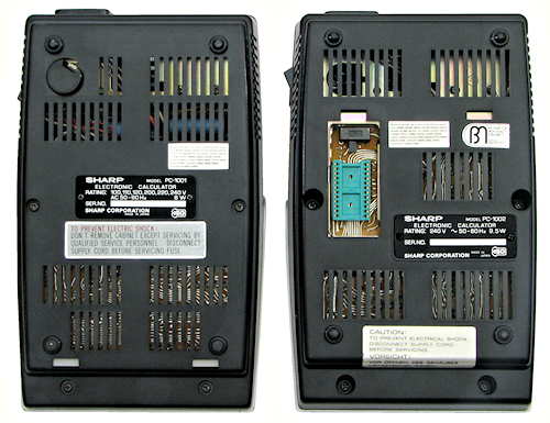
The underside of the PC-1002 (right) has a removable panel which provides access to the ROM socket and a small slider switch.
The PC-1001 (left) has a circular mains voltage selector at the top left. The PC-1002 power supply chassis has a mounting hole for the voltage selector (visible through the case slots), but the device was not fitted to this particular version.
 Component modules
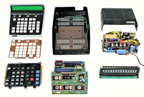
Both calculators are constructed in a modular fashion with plug-and socket interconnections. This view shows all the component modules of the PC-1001. The PC-1002 is essentially the same, but with a deeper base section and a different layout of the circuit boards.
 Processor chipset
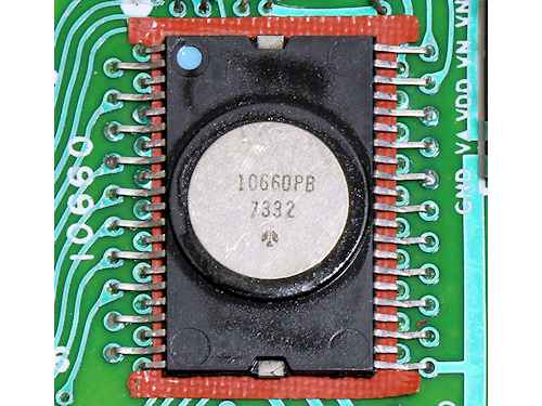
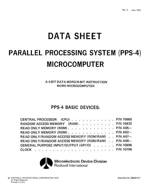
The circuitry of the two calculators is based on a general-purpose commercial microprocessor system - the Rockwell 4-bit "Parallel Processing System" (PPS-4) - rather than a dedicated calculator chipset. When introduced in 1972 the PPS-4 was the world's third commercial microprocessor system, following the Intel 4004 and 8008. The Rockwell system was similar in concept to the Intel MCS-4 system (based on the Intel 4004), and consisted of a dozen or so MOS-LSI chips, hardware evaluation modules, and software development tools.
The 10660 CPU chip is a 4-bit PMOS processor with a 2 x 4-bit data bus, a 12-bit address bus, and 12 discrete I/O bits. The processor has a repertoire of just 50 8-bit instructions. The controlling firmware is stored in two or three A05XXX 1k x 8 mask-programmed ROMs. The working registers, user memories, and scratchpad program storage are provided by a single 10432 256 x 4-bit RAM. The keyboard and display are interfaced through a 10696 "General Purpose I/O" chip with 12 input and 12 output lines (each addressed as three groups of 4).
The system runs at a clock speed of 199kHz, controlled by a 10760 clock generator (in a 10-pin TO-100 metal-can package) and a 3.579454MHz NTSC TV crystal. All of the PPS-4 chips operate from a single negative power supply of VDD = -17V DC.
The retail price of the 10660 CPU chip was $92 in 1974. The 10432
one kilobit RAM was $70 - about 60 million times the price of
RAM today (at $70 for 8 gigabytes). The GP I/O chip was $41, and the
clock generator was $29 - a total of $232 for the four system
chips alone.
PPS-4 data sheet - cover page
 Display tubes
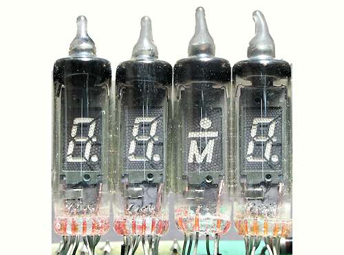
Both calculators use the same Futaba miniature fluorescent display
tubes. There are 10 tubes (type DG8R) for the main numerical display,
two more for the exponent, and two special SP8D1 indicator tubes. The
tubes are only 23mm long and 7.5mm in diameter, with 7-segment
numerals only 6mm high. The tubes have a decimal point at the lower
right, an eighth segment at the centre right which is used to display
a proper crossed 4.
DG8R numeric display
 Keyboard module
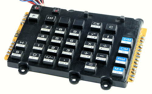
Both calculators use the same "diaphragm keyboard" module from Futaba Electronics, but with different labels on some of the keys and different connectors on the hand-wired cable. The body of the keyboard module measures 120x80mm (excluding the mounting lugs), and is only 8mm thick. A grounded copper shield plate (shown in the "Modules" view above) is mounted between the keyboard and the outer casing to reduce electrostatic interference.
 Power supply module
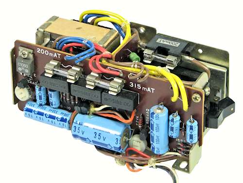
The power supply is a self-contained module built on a metal chassis at the rear of the machine. There are several versions of the supply, but all produce the same outputs. Some have a multi-tapped transformer with a mains voltage selector, others are made for only a single supply voltage, and there are different versions of the circuit board.
All versions include an IEC mains input socket, mains fuse, line filter, and power switch. The encapsulated mains transformer has four isolated secondary windings producing 8V AC (blue), 11V (yellow), 15V (brown), and 21V (red).
The rectifier board produces regulated VDD = -17V DC and VH = -5V DC for the logic circuits, and -35V and -50V supplies for the display. The outputs are connected via a flying lead and a 5-pin polarised socket. Two separate leads with single-pin connectors carry the filament supply for the fluorescent tubes.
If servicing these machines, take note that the VDD line, not GND, is connected to the metal chassis and the mains earth. A warning label was provided inside the case to advise technicians of the earthing arrangements, but the label is sometimes missing.
 PC-1001 internal view
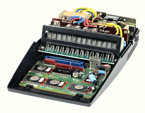
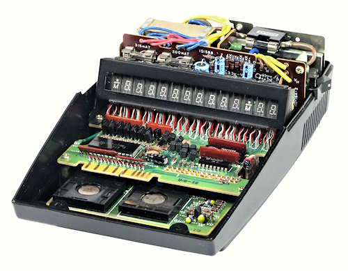
The PC-1001 circuit board is mounted at the front of the lower section of the case, with the power supply at the rear. The display board plugs directly into the main board. The boards are retained by two plastic clips at the front of the main board, and two screws at the sides of the display board. The keyboard is attached via a flying lead to the central connector.
 PC-1001 Logic Board
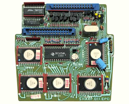
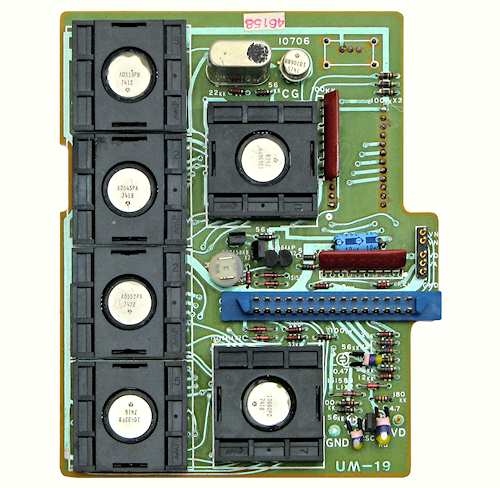
The PC-1001 has a double-sided logic board which measures about 120mm in both directions. The 5 Rockwell flat-packs (CPU, RAM, GPIO, 2 ROMs) are mounted towards the front of the board, with the clock generator and crystal in the two metal cans.
There are another 3 support chips (74154/9311, TM4356, and HD3281) and 20 discrete transistors to drive the keyboard and display. The keyboard attaches via a cable to the socket towards the centre of the board, while the display board plugs directly into the socket along the rear edge. The cable from the power supply plugs onto the pins at the centre right.
 PC-1001 display board.
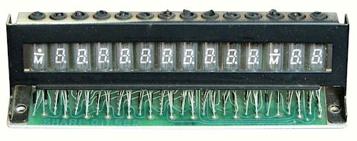
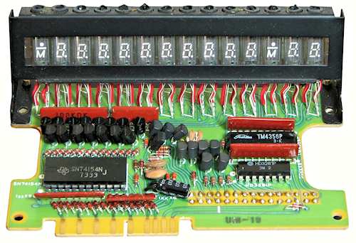
The display board carries only the 16 fluorescent tubes and the connector. The tubes are supported by a metal frame with rubber grommets around the exhaust tips at the top. The frame is attached to the base with two screws.
 PC-1001 keyboard operation.
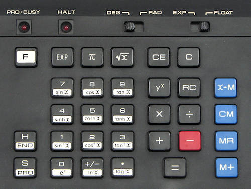
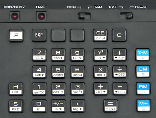
The keyboard has 31 keys arranged logically in groups (left to right) for programming, numeric entry and scientific functions, basic functions, and memory. Two slider switches select degrees or radians, and exponential or floating-point display. ("Exponential" is the same as "Scientific" mode, with one non-zero digit to the left of the decimal point). The display is always left-aligned and always shows the full 10 digits without round-off.
The programming functions are common to both machines, and are described in the Programming section below.
The scientific functions share the numeric entry keys, using the "F" key as a prefix. The PC-1001 provides common and natural logarithms, ex, trig functions and their inverses, and hyperbolic functions. There are dedicated keys for π, yx, and square root.
The power function yx is a postfix key with an unusual operation: A x B yx produces AB, while pressing Divide instead of Multiply produces the corresponding root A1/B. Reciprocals can be calculated using yx with x = -1, or more rapidly via a peculiarity of the automatic Constant function: pressing 2 x = produces 4 as expected, but 2 / = gives the reciprocal rather than 1.
The blue memory keys all require a suffix (0 to 7) to select one of the 8 internal memory registers.
The machine takes about 1.5 seconds to calculate trig functions, and over 2 seconds for powers, but the results are generally accurate to 9 figures.
 PC-1002 internal view
The PC-1002 is assembled in the same manner as the PC-1001, but has a different component arrangement on each of the three circuit boards.
The base moulding is the same shape as that of the PC-1001, but is 10mm deeper. The main board, display board, and power supply are all mounted 10mm above the base on short pillars, to make room for the ROM socket on the wiring side of the main circuit board.
 PC-1002 logic board
The obvious changes in the PC-1002 logic board are the addition of the third ROM and the use of sockets for the six flat-pack chips. This has required relocating the display and keyboard drivers onto an extended display board. The power supply pins are in the same place at the centre right, but the display board connector is much further forward than before.
A standard 24-pin x 0.6" DIL socket for the user ROM is mounted on the underside of the board at the upper right.
 PC-1002 IC socket detail
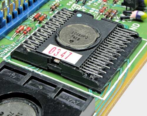
The IC sockets are in two parts. The plastic base locates the body of the chip, and has two rows of contact fingers pointing upwards at about 45°. The chip leads are left straight, and simply rest on top of the contact fingers. A plastic cover then clips over the top to apply pressure to the contact points.
The change to IC sockets may have been done to enable future CPU or ROM upgrades, or it may suggest that there were reliability problems with the earlier chips, and the sockets were introduced to simplify repairs. Unfortunately, 40 years later, the sockets themselves have become a reliability problem, with frequent calculator malfunctions due to intermittent contacts.
 PC-1002 display board
In order to provide space on the main board for the IC sockets, the third ROM, and the user ROM underneath, the display/keyboard multiplexer and the display drivers have been relocated onto an extended version of the display board. The keyboard now attaches to a card edge connector at the front of the display board. The cut-out at the right-hand side provides clearance for the power supply connector on the main board below.
 PC-1002 keyboard.
The PC-1002 keyboard is exactly the same as the PC-1001, except that more of the keys now have dual functions. The new features on the basic function keys are conversions between rectangular and polar coordinates, degrees and grads, decimal and sexagesimal degrees (ie, minutes and seconds), addition of sexagesimal degrees, and basic statistics (mean and standard deviation).
The four memory keys have dual functions labelled A, B, C, and D, which represent entry points to programs stored in the optional ROM.
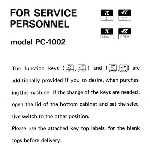
Note that there are no labels on the π and square root keys
on this never-been-used calculator. These two keys offered the
purchaser a once-only choice of their second functions - either
x! and 10x for mathematicians, or azimuth
and area calculations for surveyors. The choice was made by setting
a slider switch next to the ROM socket on the underside of the case.
The machine was packed with two pairs of alternative self-adhesive
keytop labels, which were to be affixed by the dealer before the
machine was delivered.
PC-1002 alternate keytop labels
Both calculators are capable of storing and executing simple "scratch-pad" programs entered from the keyboard. The programs are stored in the RAM chip in the same space as the memory registers, and progressively overwrite the memories beginning with register 7. Eight "orders" or keystrokes can be stored in each memory location, for a maximum of 64 keystrokes.
To record a program, press F-PRO. The PRO/BUSY lamp lights, and the step counter is set to the top of memory 7. Enter the keystrokes required. The H (for Halt) key can be recorded in the program to temporarily halt execution, so as to enter data or display intermediate results. When all keystrokes have been recorded, press F-END to exit program mode and reset the step counter to the beginning. There are no loops or conditional branching, and no provision to review or edit the program.
To run the program, check that both lights are off and press S (for Start). The BUSY lamp lights and execution begins. When a Halt instruction is reached, the HALT lamp lights and execution pauses. At this point intermediate results can be viewed, new data can be entered, or other calculations (related or unrelated) can be performed, provided they do not affect the memory registers used by the program. The program can be resumed by pressing the S key again. Execution continues in this manner until the END instruction is reached. The step counter is then reset to the beginning, the BUSY light turns off, and the calculator returns to normal operation.