 Olivetti Logos 58, S/N 3805588
Functions: ASMD, accumulating memory, printer
Technology: MOS-LSI (3 chips)
Display: Internal printer, no numerical display
Dimensions: 420W x 245D x 130H, weight 6.7kg
Manufactured: Olivetti, Italy, 1973
Olivetti Logos 58, S/N 3805588
Functions: ASMD, accumulating memory, printer
Technology: MOS-LSI (3 chips)
Display: Internal printer, no numerical display
Dimensions: 420W x 245D x 130H, weight 6.7kg
Manufactured: Olivetti, Italy, 1973
This page gives a brief description of the construction and operation of the Olivetti "Logos 58" electronic calculator. The description is also applicable (with minor modifications) to the other models of the Logos 50/60 series. General information about the Olivetti company and other Olivetti calculators can be found on the main Olivetti page.
The Olivetti company produced typewriters from 1908, mechanical calculators from the 1940s, a mainframe digital computer (the ELEA 9003) in 1959, and a revolutionary transistorised programmable calculator/computer (the Programma 101) in 1964. A cheaper non-programmable version of the P101 appeared in the late 1960s (the Logos 328), followed by the re-designed and IC-based Logos 200 electronic calculators in 1970. The 150 SSI chips of the Logos 200 machines were replaced by three LSI chips in the 200-LSI series in about 1972, and then the mechanicals were reduced to less than half the volume and weight in the Logos 50/60 series in 1973.
The Logos 58 shown here performs the four basic arithmetic functions, with provision for percentage calculations, constant storage, and accumulation of products and quotients. All entries, functions, and results are recorded on the internal printer - there is no separate numeric display.
It is recommended that readers review the description of the earlier Logos 240 machines before proceeding.
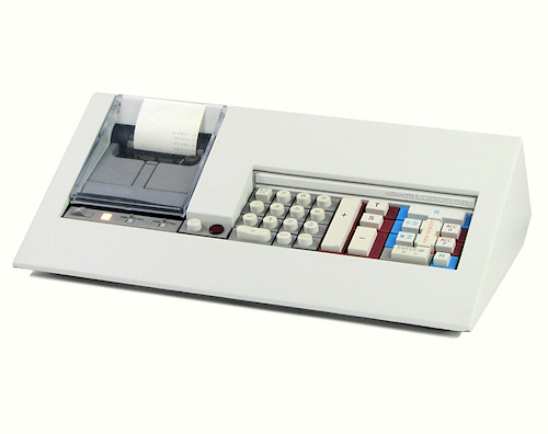
External view.
The Logos 58 measures 420mm wide x 244 deep x 130 high and weighs 6.7kg. The base and the wedge-shaped cover are of die-cast aluminium alloy. From the operator's position, the machine appears as a sloping rectangular panel which floats about 15mm above the desk.
The exterior of the Logos 50/60 series is the work of noted industrial designer Mario Bellini (1935- ), and is shown in his US patent D233346 (originally filed in Italy in October 1972).
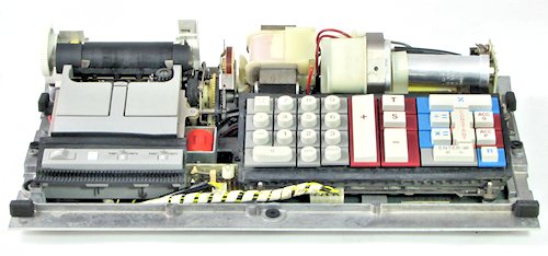 Internal view.
This view shows the Logos 58 with the cover removed. The printer mechanism is on the left-hand side, with a small control panel at the front. The drive motor for the printer is at the centre rear, with the power supply at the right. The electronic circuitry is all contained on a single board which is mounted under the right-hand side of the machine.
The Logos 58 continues the principles of modular design from the earlier machines. Assembly and maintenance are greatly simplified by building the machine as a series of self-contained units, each with clearly-defined functions, simple mountings, plug-and-socket wiring, and an absolute minimum of interconnections.
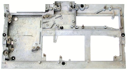 The baseplate.
The mechanism is built on a die-cast baseplate measuring 410 x 230mm. The front section is 15mm deep, with a raised section 30mm deep at the rear. The main circuit board is mounted in the 15mm space under the baseplate, with plug-and-socket connections passing through the three large cut-outs. The circuit board is protected by a pressed-metal panel which covers most of the underside of the machine.
Steel locating pins are provided to hold the various modules in position, and to ensure that the keyboard and power supply mate correctly with the pin-and-socket connectors on the main circuit board below.
The upper section of the casing rests on rubber-covered pads and bushings, and is secured by captive spring clips at each end of the machine.
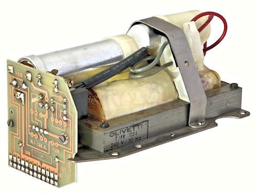 The power supply.
This view shows the power supply module from the rear. The mains input to the power supply is via a moulded connector under the metal strap, while the DC output is via the pin-and-socket connectors along the bottom of the circuit board.
As in the earlier machines, the power supply uses a constant-voltage transformer to provide a regulated AC input to the rectifiers. A centre-tapped winding produces + and - 12V DC supplies for the logic circuits, while a separate winding produces +12V for the printer solenoids.
The nameplate power rating is 240V 75W, but the consumption with the machine idle is only 16W. The AC induction motor draws another 40W while printing, and the solenoid supply provides instantaneous peaks of up to 20W.
A small mains wiring loom interconnects the IEC input socket, the power supply, the printer motor, and a switch module and mains fuse mounted under the printer. The power and motor switches are operated by mechanical linkages so as to remove the need for mains connections to the control panel or the printer.
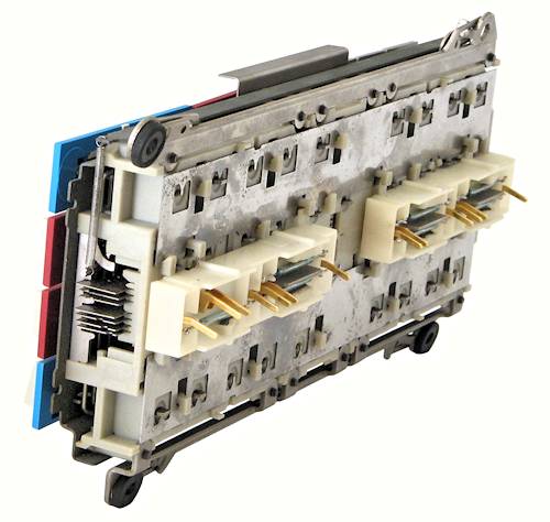 The keyboard
The Logos 50/60 machines still use a mechanically-encoded keyboard, but do not have the power-assisted mechanism of the earlier versions. The simplified design is much less positive in feel and action.
At the rear of the keyboard are seven glass reed switches and their operating magnets, housed in two clip-on plastic mouldings. The magnets are coupled to the seven code bars, which run lengthwise through the centre of the keyboard.
The keys are coupled to a set of plain wire bails which engage with ramped slots in the code bars. Pressing a key forces its bail down into the slots, thus moving the corresponding codebars lengthwise and setting the associated reed switches. Every key operates the first code bar to generate a strobe signal (except for the Constant key, which only acts as an auxilliary to its adjacent keys).
The basic mechanism has provision for four rows of ten keys. It could be reconfigured to suit the different Logos 50/60 models simply by changing the keytops and the corresponding code bars.
The keyboard module sits in rubber bushings on four locating pins on the baseplate, and plugs directly into to the main board below. The entire keyboard assembly can be removed in an instant by releasing four sliding latches at the corners.
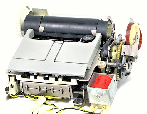 The printer mechanism.
The Logos 58 uses a small plain-paper impact printer of Olivetti's own design. The mechanism is described in US Patent 3876053, first filed in Italy in January 1972.
The printer uses a cylindrical print head with two rows of 12 characters. One side has numerals 0 to 9, comma, and decimal point, while the other has 12 places for symbols. Five small solenoids along the front of the machine engage with rotating cams to position the print head for the required symbol or number. The unit prints from right to left, with two columns of symbols at the right-hand side and up to 20 columns of digits. The printer uses a black fabric ribbon only 5mm wide, in a cartridge just slightly smaller than an audio cassette tape. The paper roll is 75mm wide and is supported on folding arms attached to the top cover of the machine.
The mechanism is driven via a toothed belt and reduction gear from a small shaded-pole induction motor, which only runs while the machine is actually printing. The operation is controlled by a large solenoid (front right) which engages the main clutch, and a microswitch (front left) which senses when the print head is in its home position. The printer connects to the main circuit board via a 10-wire cable from the five selector solenoids, and a separate 4-wire cable from the clutch solenoid and home sensor. There are no electronic components in the printer itself - all of the logic and driving circuitry is on the main circuit board.
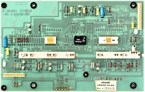 The circuit board.
The Logos 58 uses a double-sided circuit board measuring 260 x 160mm, which is mounted component side up under the baseplate. The power supply connects to the pins at the top right; the control panel to those at the bottom left. The white mouldings along the centre of the board contain the sockets for the board locating pins and for the keyboard connectors. The two printer connectors and the six solenoid drivers are along the bottom of the board.
The main processor (in the centre of the board) is a Texas Instruments TMC1828 in a 16-pin x 0.6" DIL package. This is supported by two custom interface chips from AMI, labelled LOG1876 and LOG1877. The chip date codes are from weeks 20, 22, and 23 of 1974. The two-transistor clock oscillator at the top of the board generates complementary square-wave clocks at 500kHz.
To remove the board it is only necessary to un-plug the printer and the control panel and to remove the bottom cover (4 screws). The board can then be lifted straight out via the plastic handles provided.
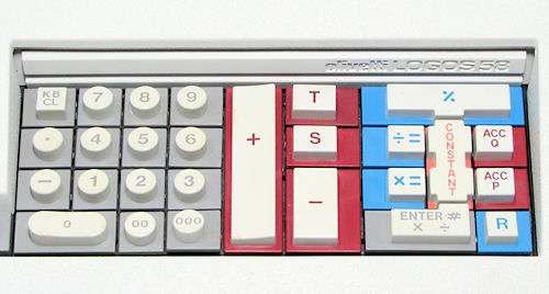 Keyboard detail.
Operation of the Logos 50/60 machines is essentially the same as described previously for the Logos 200 series and is not repeated here.
The Logos 50/60 power, roundoff, and decimal switches have been relocated to a small control panel in front of the printer, as shown in the top photo.
The Logos 58 adds a percentage function and a second accumulation function (Acc Q) for quotients, but is otherwise similar to the Logos 240 described previously. More elaborate models included square and square root keys, and a second independent accumulator with its own Add, Sub, S and T keys.
I would be grateful to any readers who could supply English versions of the technical or user instructions for any of the Logos machines.